How To Make Needle Valves and Spray Bars
Click on photographs to view in more detail


Making needle-valve/ spray-bar assemblies--NVA's for short is a tedious but relatively simple process that can be carried out on even the smallest and most modest of lathes. I know model engineers who keep a little Taig, Sherline, or old round-bed Drummond just for operations like this. No great accuracy is required, though good precision is.
First, let's review what we require in an NVA. Most importantly, it needs to meter the fuel supply in a consistent and reliable way, supplying the fuel as tiny atomized droplets. We achieve this by ensuring that the metering occurs at the inlet, not the outlet. And it must supply only fuel. If it leaks air, the mixture will probably undergo large and unpredictable changes as the needle is adjusted, making the engine hard to tune, or even prone to sudden stopping.
Lastly, if it's a replacement for an engine that's come to you without one (the most likely scenario--countless old engines are in this state), you'll almost certainly want it to look as close to original as possible. If the engine is to run, you also want it to be soundly made and capable of accurately metering fuel! This is not so simple and was the topic of discussion in the February 2003 Issue of Model Engine News. I suggest you click on the link and review why an accurate needle seat is essential to harmonious operation.
 If you have, or can borrow an engine that still has a complete, original NVA, problem solved--make a simple sketch of the important dimensions and away you go. If not, check out old magazine engine reviews and other sources for a drawing or photo. The early reviews in the Aeromodeller and Model Aviation are good sources of relatively accurate, full-size 3-view drawings of many old English, Australian, and even some American engines. They won't give you the thread size, but we can make an educated guess on this. Determine the spray-bar diameter by poking number drills into the venturi hole (which hopefully has not been drilled out by some ancient butcher). Now look at a table of threads appropriate to the engine source. English and Australian engines up to the 70's will generally use a British Association (BA) thread. After this they will probably be metric. There are exceptions--some used 1/8" Whitworth, a 40 TPI thread, but most were BA. American engines will be UNC, or UNF. The venturi spray-bar hole will be close to the major thread diameter and you'll probably get it right, or close enough for government work.
Now armed with a simple rough-sketch, we can make a start. Unfortunately, magazine reviews seldom mention what the NVA's were made from. But if in doubt, brass is usually a good guess. A few, like the AM series, used aluminium for both needle thimble and spray-bar. Some DC engines like the Merlin and Spitfire had an aluminium thimble on a brass spray-bar, but most were all brass. The common "stock" sizes for thimbles and spraybars are 1/4" and 3/16" round brass, and 1/4" AF hexagonal (AF is short for "across the flats"). It's a good idea to keep a stock of this, and other AF hex sizes "in the rack" as most NVA's do not use stock nuts, rather they are made from a smaller size of hex stock than the size common for the thread--and nothing stands out worse that a giant, plated nut in place of a smaller, elegant, plain brass one. I've frequently made replacement nuts by drilling out and re-tapping a smaller size nickel-plated brass nut, thinning it down, then carefully filing the plating off the hex sides.
Enough yabbering; on with the machining. For this exercise, we'll be making an NVA for an ME Heron, a 1 cc diesel from the Isle of Mann, built in the 60's and available in air and water cooled versions:
 Step 1: Start with the thimble. There's a very good reason for starting here, namely, because threading dies are adjustable, but taps are not. We want the thimble to be a close fit on the spraybar to ensure concentricity and prevent air leakage. If the thimble is available when we cut the spray-bar thread, we can ensure this is so. So chuck the thimble stock and blind-drill to the required depth with the recommended tapping size drill for the thread. If the thimble requires knurling, do this first as it's a violent operation and will have adverse effects if done after drilling and tapping.
Now change to a drill a couple of number sizes less than the wire you will use for the needle. If the wire being used is 1/16" diameter (0.062"), use a #54 (0.055") drill. Blind-drill this size for sufficient depth to extend past the end of the thimble. Now open out to 1/16". Twist drills will always cut oversize. Doing it in two steps minimizes the error and should give a loose, but not too loose fit on the wire, suitable for soldering and concentric with the lead-in hole, which can now be tapped.
When tapping, turning the chuck by hand, reversing the chuck every half turn for at least a quarter turn to break the chips. I tighten the Jacobs chuck on the tap by hand rather than using the chuck-key. This ensures that if the tap gets tight, it turns in the chuck rather than breaking. Start with a second taper tap and finish with a bottoming tap. Finally, part off to length and dress up the end as required.
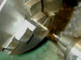
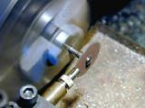 The thimble for the Heron should have been "slit". This allows the thread to be closed up to get a reasonable amount of friction to prevent the setting wandering. I did not bother in this case as the thread fit was good, but if you need to slit the thimble, do so after tapping, but before parting-off. I've used both thin slitting saws and Dremel cut-off disks for this task. The latter will make a cut about 25 thou wide which is bordering on too large (0.016" seems to have been the popular slitting size). Mount the saw in the chuck and the thimble in a tool holder. Advance the thimble using the compound slide until it touched the face of the (stationary) saw. Back it away from the saw with the cross slide and advance further with the compound by an amount equal to one half the sum of the thimble diameter plus the saw thickness. Start up and plunge the thimble into the saw (having first adjusted the thimble to be centered on the lathe spindle height). Neat, easy, fast (and extra points for those who can identify the thimble being slit in this photograph).
 Step 2: Grip the spray-bar stock with just enough protruding to form the reduced diameter down to the shoulder, plus a quarter inch (6mm) or so. We want the shank, thread, and needle hole to be concentric, so don't move the part in the chuck until all operations are finished.
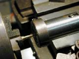
First, form the spray-bar shank. If your tool is sharp and you only remove say 10 thous of diameter per pass, you can avoid having to use a dead center support and still end up with a parallel shank. The Heron spray-bar seen here has a 5BA thread, so the major diameter is just 0.126" diameter. It was turned with no support and no taper, but with a very sharp tool. Check after making a couple of passes by measuring at either end. More than 0.002" difference is too much. If you need to support the stock with the tailstock, you can use a "half" dead-center that will allow you to cheerfully produce shanks down to 1/8" diameter. In this case, you'll need to increase the overall shank length a bit so you can face off the sharp edge.
Mark where the thread should be cut too with a grease pencil and open up the die in the adjustable tail-stock die holder as far as it will go. Bring up the die and again rotating the chuck by hand, cut the thread reversing as before to break the chips. If all is well, your thimble should not fit. Incrementally close up the die and hand turn another pass. This produces a nice, clean thread, the aim being to achieve a firm, but not tight fit in the thimble.
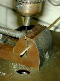
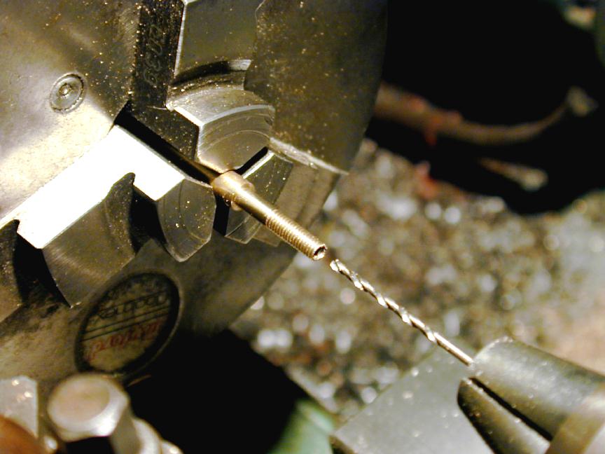
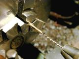 Step 3: Now we can drill for the needle wire. Don't do this before cutting the thread as there is a very real danger that threading would twist, distort, or snap the thin-wall tube were we to progress the other way around. First, center-drill, then chuck the "2 sizes under" drill and blind-drill to within 1/16" or so of the shoulder (this not critical, we just want to ensure that the needle positions so that the spray-bar holes are never closed off by the needle and all fuel-metering takes place on the yet to be formed seat).
Brass chips won't clear easily from small twist drills, so I "peck" away with a sash-brush in my left hand and the tail-stock wheel in my right: drill another 1/16", withdraw completely, brush away chips, peck again. This achieves two things. First, it prevents the drill jamming and breaking, and second, helps the drill cut closer to size and minimises wandering. Both are good.
 Step 4: The "seat" for the needle is now formed by changing to a #60 drill and blind-drilling another eighth-inch or more. The point left by the #55 will neatly start the #60 concentrically for the all-important fuel-metering shoulder. As drill size goes down, "pecking" out holes to avoid broken drills becomes more important, and the amount drilled with each "peck" should get smaller. A drill whose flutes are clogging up in brass will squeal most distressingly--don't ignore this sign!
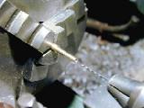
 Step 5: We want the hole for the needle to be a close fit on the wire, and the only shure-fire way I know of achieving this is to ream the hole with a D-bit made from the needle-stock wire. As seen here, the "D" is not very long, so frequent withdrawals to brush away chips are required. The D itself is about 0.001" more than one half the measured diameter. It can be successfully formed by careful application of a cut-off wheel in a Dremel hand-tool, but it's much easier and more accurate if you have something like The Quorn available.
Check when finished that your actual needle wire is a close sliding fit in the hole. If it's loose, your D-bit reamer is blunt. It still may be usable, but there is now the danger of air leaking around the needle wire, making the needle difficult to adjust (the engine will be "critical" of needle adjustment, prone to unexpected stopping during adjustment). If it won't fit at all, the wire must be different! This happens and the cure is make another reamer from the wire you're going to use.
 Step 6: All the serious concentric operations are now complete, so we can drill the spray-bar hole(s). For one-off jobs, I generally pop the spray bar into the venturi and mark the location with a scriber or pencil using the Mark I Eyeball to center it. The stock material provides a handy way to hold the part for this step, so don't be premature in parting it off yet. Use a #0 center-drill to locate the point for the hole on your mark, and as centered as possible on the bench drill, or mill. Change over to the ubiquitous #60 drill and drill through for a two-hole spray bar (like the Heron here), or just to break through to the needle wire hole for one-holers.
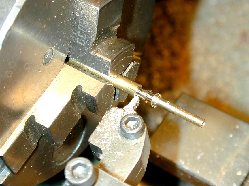
 Step 7: Now back the lathe to form the fuel tube nipple profile and for parting off. The Heron nipple is of what I call the "bayonet" variety--a tapered end with a shoulder. The shoulder should be rounded slightly. If left sharp, it may cut modern silicon-type fuel tubes (there was no such danger on the older, so-called "neoprene" clear tubing, unless it was to the spray-bar!) The other popular style has a rounded ridge with parallel sections either side. This sort can easily be formed using a form-tool made by grinding a shallow, narrow, arc into the end of a piece of 1/8" square HSS with the universal Dremal cut-off disk.
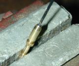
 Step 8: The spray-bar is completed by gripping lightly on the shank and running in a #0 center-drill in so that a light cone is formed on the inlet side as seen here. If you guestimated correctly on the #60 blind hole drilled in step 4, the center-drill will connect with this hole and the part is finished. If not, take a quick peck from this side with the #60 to join up--but don't run the drill through! This would run the danger of oval-izing the fuel metering hole due to minor concentricity issues (unless the spray-bar is being gripped in a collet). Better not to tempt fate.
 Step 9: Finally, comes the needle part. Thick darning needles are a good source of needles for shorter needle valves, but the Heron requires a wire end that's long and bent over, so we need to grind our own on a piece of 1/16" diameter music wire. Ways of achieving acceptable results are fully described on
the Needles How-to page.
Assuming we now have the needle formed, we come to the part that can make or mar the finished appearance: soldering the needle to the thimble. Making neat yet strong solder joints is easy, yet so often I see nice workmanship marred with an unsightly blob of solder that's gone everywhere and is obviously a failure waiting to happen. The technique I use was once called "sweating", and here's how to do it.
Step 9: Finally, comes the needle part. Thick darning needles are a good source of needles for shorter needle valves, but the Heron requires a wire end that's long and bent over, so we need to grind our own on a piece of 1/16" diameter music wire. Ways of achieving acceptable results are fully described on
the Needles How-to page.
Assuming we now have the needle formed, we come to the part that can make or mar the finished appearance: soldering the needle to the thimble. Making neat yet strong solder joints is easy, yet so often I see nice workmanship marred with an unsightly blob of solder that's gone everywhere and is obviously a failure waiting to happen. The technique I use was once called "sweating", and here's how to do it.
There are three basic rules to good soldering: cleanliness, cleanliness, and cleanliness. We've just drilled the thimble hole (dry, no lubricant) and faced the end, so they are clean. The wire is easy to clean by rubbing it in a piece of folded over 600 grit wet-and-dry sandpaper (dry). Keep this up until the wire is absolutely bright and shiny, then wipe with a clean rag.
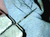
Screw the thimble home all the way, then back off a turn (checking that enough spray bar is exposed to span the venturi and take the securing nut). Now push the needle in until it is firmly against the seat. Mark the exposed wire about 1/16" from the end of the thimble with a grease pencil. Remove the wire and make another grease pencil mark about 1/4" towards the pointy end from the first circumferential mark. We will now "tin" the area between the two marks. The grease pencil will prevent the solder from spreading any further than the marked out band.
Hold the wire horizontally in a vice. Melt some 60/40 rosin cored solder onto the tip of your iron (a 60 Watt job is more than adequate). Touch this to the underside of the wire. Apply more solder to the wire itself above the iron tip. When the wire is hot enough to melt the solder, form a big, unsightly blob all the way around the wire. Stroking the wire with the iron tip will help. Now quickly put down the iron, and wipe the molten blob off with a rag. The result is seen in the photo above: a dullish silvery area where the solder has actually wicked into the steel wire. As it is IN the wire, the diameter will be the same as before. Examine closely to make sure there are no places where bare metal is visible in the tinned area.
 Step 10: Now slide the needle back onto its seat. The tinned area should extend from just after the spray bar end, under the thimble, to just past its end. If the tinned area passes into the spray-bar, we're in danger of gluing everything shut (yes, I've done that), and the needle and thimble must be unscrewed in unison the get the tinned area out of the spray-bar. This is why the grease pencil limits are so important. Assuming all is well, we can wipe all solder off the tip of the iron and apply the tip to the exposed tinned section of the wire and let it heat for a few seconds. Now apply just the tiniest bit of solder to the junction of wire and thimble. If it does not melt, take it away. When both are hot enough it will melt and flow around the end of the thimble.
An alternate way is to use no extra solder at all, and heat the wire and thimble with a direct gas flame. It's amazing how the solder abruptly beads up, apparently appearing from nowhere, forming a neat, almost invisible joint. Be very careful not to bump anything until it cools. Any movement while the solder is mushy will cause a "cold joint". Cold joints are dull in appearance and will fail. Don't force cool by dunking is water either--this is another way of ruining the joint.


Bend over the end, make the nut, and the job is done. That's all there is to it. My workshop notebook has all sorts of NVA drawings scattered through it. Some day, in my copious free time, I plan to clean these up and make them available via these web pages. So much to do... so little time...

This page designed to look best when using anything but IE!
Please submit all questions and comments to
enquiries@modelenginenews.org
Copyright (c) Ronald A Chernich, 2004-2005. All rights reserved worldwide.