Weaver Construction Log Page 5.
![]()
Conrods and Crankshafts (December 1999)

A crankshaft has two bearing-quality fits to be finished: the main journal and the crank-pin. We can check the main journal fit in the crankcase, but the crank-pin must be a close, working fit in a hole we have not reamed yet, so the conrod gets made next. In this picture, the conrod material (1/8" thick gauge plate) is resting on parallels while the holes for four rods are drilled and reamered. This ensures all holes at least start out parallel to each other.
 After the holes are finished, the blanks will be sawn apart (you may just be able to make out the scriber lines).
The plans give the diameters of the small and big ends as 0.156" and 0.188" respectively. We can reduce the amount of difficult, tiresome, fiddly filing needed if the rods can be profiled as much as possible under the mill. With a little head scratching, you can figure out the diameter of the rods needed so the blank rests at about the right angle to profile the sides. With the quill downfeed locked, a trial cut is made on one side, then the rod is flipped and the second side milled. At this stage the width at one hole diameter is measured and the quill lowered by half the difference from the required size. All rods can now be run through.
After the holes are finished, the blanks will be sawn apart (you may just be able to make out the scriber lines).
The plans give the diameters of the small and big ends as 0.156" and 0.188" respectively. We can reduce the amount of difficult, tiresome, fiddly filing needed if the rods can be profiled as much as possible under the mill. With a little head scratching, you can figure out the diameter of the rods needed so the blank rests at about the right angle to profile the sides. With the quill downfeed locked, a trial cut is made on one side, then the rod is flipped and the second side milled. At this stage the width at one hole diameter is measured and the quill lowered by half the difference from the required size. All rods can now be run through.
 After all this time, you'd think I knew what one eighth of an inch looked like! Wrong. Turns out the gauge plate material used for the conrods was 4mm thick - over a thirty-second thicker than needed. This fits, but is in danger of causing the big end to rub against the backplate when the crankshaft is at the aft-most point of the end-play. At this late stage, gripping the blanks for thinning is difficult. Fortunately, I have a little Myford milling vice which has one floating, pivoting jaw. This allows the rod blank to be setup on a parallel and tightly gripped on the tapered sides. I could have used the mill to remove the offending material, but my latest toy (which followed me home from the US, taking over a year to get here) is a 7" shaper off a WWII battleship. This photo shows a conrod blank after the shaper has reduced it to .125" thich, as required. Note how all cutting forces would tend to tighten the part in the odd little vice. Pwheh! Now all that needs to worked out is how to finally profile these rods.
 To hold the rods for taper turning the center portion, I made two jigs, slit on the end to be a tight fit on the material thickness and drilled to take screws that would clamp up the forks tight on the blanks. The big end jig is gripped in the three jaw chuck. The other end has a 1/4" stub (not visible) that runs in a bronze bush held by a drill chuck in the tailstock. The bush is brought up firmly against the sholder of this jig. When everything is tightened up, the rod will run true with no slop, as good as if it were between centers. The taper was cut with the compound slide set over one degree using a tool ground from 1/4" diameter HSS in a George Thomas holder. This has a side benefit of assisting the compound slide handle clear the tail stock. The photo shows the cut progressing.
As usual, the lathe chuck was mounted on the rotary table under the mill to make the jigs. The screw hole was drilled first, then the saw brought to near center height and a cut made. The part was rotated 180 degrees and another cut made. This ensures the slot is equally disposed either side of actual center. The slot width can then be measured and the saw raised by half the difference between measured size and required size. Two more cuts, again rotating 180 degrees between them, and the jig is done. There may be a better way of doing this, but it seems to have worked well for me. When turning, the tool would not reach right into the sholders (as can be seen in the above photo). So after the approximate size had been reached, the tool was jiggled to reach in and remove the metal right up to the jig faces.
 The two rod ends were profiled with a 1/8" diameter end mill using a small hand-operated rotary table held on parallels in the milling vice. The rotary table itself is the fameous George Thomas design published in Model Engineer in the late 1970's. A kit comprising drawings, instructions, base casting and stock for the table and pivot is available from Hemingway in the UK. It may not get a lot of use, but when it is used, it is absolutely invaluable. Be sure the cut is made using "climb milling" - ie, the direction of tool rotation opposes work rotation. Cut was put on ten thou per pass.
The center of the table post is reamed 1/4" diameter, so simple jigs are made from 1/4" brass rod to accurately center and hold each rod end. The opposite end is clamped using a smaller insert attached to the T-Nut, so each rod is firmly held in the same position allowing the end-stops to be adjusted once for all rods. One of these end-stops can be seen underneath the handle in the photo. Initial adjustment of these is a cut and try operation that needs to be done when the final OD for the end has been reached.
 This shot shows some before and after profiling examples. A little work still remains to be done with the needle files to flair in the profiled section to the tapered section, but not a lot. Finally, the rods will be polished with wet 'n dry, "tweaked" by measuring between lengths of drill rod to ensure the two holes are parallel, then hardened and tempered, quenching in oil. The rod at the top of this shot is a test piece that got a bit mangled (look at the shaft just beside the little end) while I was working out the procedure - forgot to clamp the tool block in the Myford-Dixon holder - bang - thrash - strong language - stuffed and thoroughly bent rod. *sigh*.
At this point, with the benefit of hindsight, I may as well mention that all the milling and pre-profiling I went through for the rods was completely unnecessary! They could have been left rough cut as they came from the band saw as every part of them (except the stock thickness) is machined in subsequent operations. Still, looks good in the photos. 
The original Weaver was fitted with a flywheel using a "Westbury Atom" style collet. "Aero-izing" the engine requires a prop drive washer. Normally, I'd use a brass split cone to secure the driver, but the sizes involved decided me against this. Instead, I've used a slow taper on the shaft to secure the prop drive washer. Diameters involved dictate this be about 4 degrees, a size for which I've no pre-made reamer, so as I've not documented making taper d-bit reamers anywhere else, here are a few tips on how I go about it. As usual, my description is not necessarily the right, nor only way - that's for sure!
 My d-bit reamers are made from water hardening drill rod. I find this stuff ugly to machine, but with sharp tools and patience, the job gets done. The taper can be turned by setting over the compound slide by half the included angle, or by using a taper turning attachment, if you have one. My Myford has one, made from a Hemingway kit, so that's how I went. When finished, the thickness of the "D" should be just less than half the original diameter. There is a formula for determining how much "just" is, but for bits in the 1/4" major diameter range .002" is near enough. In this photo, the bit has been tapered and is being rough finished using a 1/4" end mill. I'm ab-using the Myford-Dixon adjustable toolpost holder as an adjustable vertical slide to mill away the bit. It's a hit-n-miss adventure, but with frequent measurement and small increments, I can get to within two thou of finished size easily enough.
 After roughing to size, the bit is heated to cherry red and quenched vertically into a water container. The tip of this tool is 1/8" in diameter, so provided the plunge is vertical, there should be no distortion problems. Now hardened, the bit must be tempered. To do this, the scale is buffed off and the shank heated until the tip just reaches a "straw" color, then quenched again. The d-bit was brought to final size using my Quorn cutter-grinder and finished on an oil stone, as seen in this photo. It's only going to cut aluminum, so it will probably last a lifetime. I stamp the end of the shank with the included taper of the bit and make an entry in my workshop inventory that I now have a 4 degree D-bit reamer (someplace :). If you squint carefully at this shot, you can see that I've turned a short length (about 1/32") of the very tip parallel to a known size - 0.120 in this case. This makes for a place to put the digital calipers when grinding to final size that is easy to measure.
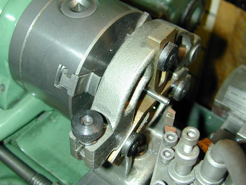 Crankshafts, as I've mentioned elsewhere, are feared by beginners, but not that difficult to make a good job of. Here, I'll just cover aspects not detailed previously, or that are specific to the Weaver. In this photo, the shafts have been been turned and lapped to a running fit in the crankcase journal. The crank web and allowence for the crank pin provide an area to grip while doing this. In this photo, the half-centre used to support the shaft has been removed and a fixed steady brought up for support while the taper for the prop drive washer is turned. I'm using screw in studs (6-32) rather than going to the effort of machining a delicate threaded end on the shaft.
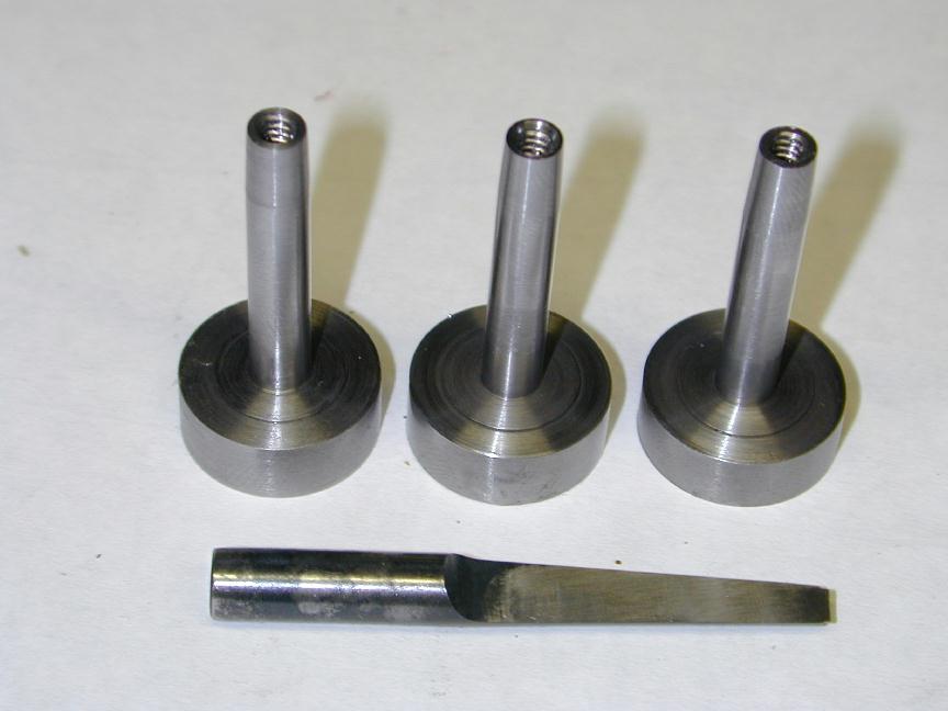 And here are three blanks, lapped, tapered, tapped and ready to for crank pin machining. The D-bit in the foreground was used in conjunction with a DTI to setover the compound slide when tapering the end. With care, this will produce an acceptable mate between propdrive washer taper and shaft end taper. The 0.010" thick "thrust face" on the front of the crank web is also visible. This reduces friction in the area where prop thrust is transferred to crankcase and from that, to the airframe.
 The crankpins will be turned in a jig similar to that used on the
EZE series. To make the jig, saw, or part off a section of aluminum bar stock of radius at least 1/8" greater than the crank throw plus one half the shaft diameter. Face the ends and set it up, offset from center in the four jaw chuck by the throw. I do this using a plunger type dial test indicator (DTI). Set the plunger at right angles to the undrilled jig and zero it at the minimum reading rotation of the work. Jiggle the jaws until the DTI reads twice the throw at the maximum reading point. This is a multi step process as each adjustment will change the zero reading, but it does not take long. Tighten up; center drill, drill and ream, then saw through the hole to a point near or past the center of the jig. This photo shows the jig just after center drilling. Surprisingly, when gripped in a three jaw self-centering chuck in good repair, this gives adequate crankpin geometery for sport engines.
The crankpins will be turned in a jig similar to that used on the
EZE series. To make the jig, saw, or part off a section of aluminum bar stock of radius at least 1/8" greater than the crank throw plus one half the shaft diameter. Face the ends and set it up, offset from center in the four jaw chuck by the throw. I do this using a plunger type dial test indicator (DTI). Set the plunger at right angles to the undrilled jig and zero it at the minimum reading rotation of the work. Jiggle the jaws until the DTI reads twice the throw at the maximum reading point. This is a multi step process as each adjustment will change the zero reading, but it does not take long. Tighten up; center drill, drill and ream, then saw through the hole to a point near or past the center of the jig. This photo shows the jig just after center drilling. Surprisingly, when gripped in a three jaw self-centering chuck in good repair, this gives adequate crankpin geometery for sport engines.
 The prop driver is turned from aluminum and reamed with the D-bit, giving it a taper to match the shaft.
In this shot, a driver is being parted off using a band saw because (1) it's easy and less drama than parting it off, and (2) there's less waste! The two grooves are purly decorative, reminiscent of an AMCO. After parting, the driver is reversed in the lathe, faced and knurled.
The reaming is a hit and miss operation since trial fitting will not force the shaft onto the taper as far as the prop nut eventually will. I find it best to err on the too much side and face back the prop driver in a pot chuck later to get the desired amount of shaft end play. If the taper is too shallow, we'd be in trouble as not only would it be difficult to re-allign for more reaming, the pot chuck would only be gripping on a 1/32" wide band making for a delicate setup.
The prop driver is turned from aluminum and reamed with the D-bit, giving it a taper to match the shaft.
In this shot, a driver is being parted off using a band saw because (1) it's easy and less drama than parting it off, and (2) there's less waste! The two grooves are purly decorative, reminiscent of an AMCO. After parting, the driver is reversed in the lathe, faced and knurled.
The reaming is a hit and miss operation since trial fitting will not force the shaft onto the taper as far as the prop nut eventually will. I find it best to err on the too much side and face back the prop driver in a pot chuck later to get the desired amount of shaft end play. If the taper is too shallow, we'd be in trouble as not only would it be difficult to re-allign for more reaming, the pot chuck would only be gripping on a 1/32" wide band making for a delicate setup.
 On this journal's front page is a Weaver built by Russell Watson-Will. Russ wanted a nice long shaft so the engine could be completely enclosed in the cowel of small free flight scale models. To do this, he kept the standard crankcase size, but used a prop driver almost as long as the main journal! He also burried the crankshaft stud (a 6-32 cap head screw with the head cut off) inside the prop driver and prop nut so that the prop nut has a 3/16" diameter portion that enters into the prop driver - a'la Oliver Tiger. The prop sits on the nut which is the correct diameter for props in the 7 to 8 inch diameter range and the nut is accurately alligned by the hole in the driver. This seemed like a good idea, so I've copied him. In the foreground are the parts, while on the right is an engine, sans prop, and on the left, one with an 8/4 prop fitted.
![]()
Back to Weaver Journal front page