WATZIT?!
Model Engines of Unknown Origin
Page 6
Last update: November 2009
Click on images to view them in larger size and more detail.
Nice, but Complicated
 |
 |
 |
 |
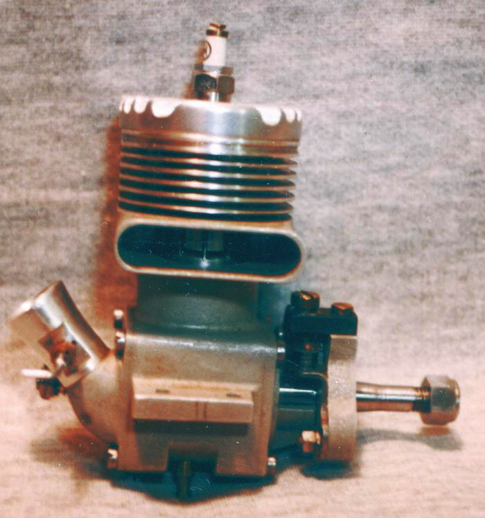
If there's any substance to the old one about the British being renown for finding innovative and complex engineering solutions to non-problems, this one must be English! Our puzzle engine is a large sparker, very nicely made with a number of unusual and distinctive features. Most obvious is the way the designer moved the timing adjustment lever to the rear of the engine, taking fingers out of harm's way. The rear of the engine appears to carry a pump, with the rather small fuel tank attached by three stand-offs and providing the bulkhead mounting flange. All castings are very nicely done and fit together quite well. The rather coarse needle valve ratchet argues for a fine thread, if "one click" is to have only a small incremental effect. Last clue: if you've studied these pages diligently, then you've seen this engine's brothers and cousins a number of times before, including a 18 cylinder radial from 1936.
The Answer:
 |
 |
 |
The engine is a Gerald Smith Redwing 7.5cc, a number of which, together with the larger 10cc Lapwing and 15cc Magpie are shown here as part of a very extensive GS display at the Midland 2005 Model Engineering Exhibition before the collection was broken up. Note the different orientation of the heroic needle clicker on the display engines from out Watzit photos. This is not an assembly error: upright and inverted models were customer options. At first glance, the case may appear split; it's not, that's just the casting parting line. The pip which looks like a sump drain in the middle of the bottom of the case is actually a center support used while turning the cylinder head fins. The cylinder is integral with the case and was painted as seen in all the photos. The long screws which hold it all together secure either the bulkhead mounting fuel tank, or the rather delicate looking and severely over-hung "lug" mounting castings. I'd feel uneasy about those when using a pull-cord on the flywheel.

Gerald Smith's single cylinder spark engines date back to just after World War II with the lifting of the ban on model flying in Britain and release of "strategic materials" for more pleasurable pursuits. This little advertisement appeared in the Aeromodeller of November, 1946 (p736). The singles shared a common case, varying only the bore and stroke, but you can tell the difference without disassembly by counting the head bolts. The 7.5cc "Redwing" had four bolts. The 10cc "Lapwing" had six, and the 15cc "Magpie" eight. Between 1946 and 1949, Gerald Smith hand made about 35 Magpies, 160 Lapwings, and 65 Redwings. Engines could be ordered for radial mounted upright or inverted aero use, or bearer mounted with flywheel and optional ducted cooling for marine or tether car use. There was also a 10cc Wizard racing engine of which about thirty were made, only one of which was an aero model. Thanks go to Motor Boy Eric Offen for his wealth of knowledge on these engines and photos of those in his collection.
See also: David Janson's GS Skylark review.
Not a Tempest and not a Hurricane
Here, for a change, is an engine we have no idea about, but rather think we should. Most obvious, it's a 10cc sparker almost certainly intended for tether car application. It shows influence of "modern" design, so we guess it comes from the late 40's to early 50's. We have reason to think it is Australian (but it's not a Tempest, and it's not a Hurricane). The engine is in the extensive collection of the late Leo O'Reilly, the owner of the "Modelflight" stores downuder and a major importer of modelling goods for sale to the Trade. If anyone can help, email through the address at the bottom of this page.
An Ill Wind

Not only have I made a bad pun, I've probably given the identity away as well. This beautiful photo of a rather sick old sparker was taken at Old Warden, September 2010. It has low compression and is missing a few obvious bits, plus the piston (which may explain the compression). Note the precision fit of the case halves, the odd mix of fastners, and the lack of holes in the mounting lugs! All this would normally argue for a one-off homebuilt, but maybe not. So what do you think it is?
The Answer:
 It's a Model Dockyard Whirlwind. Model Dockyard was a meca for model makers located in a basement off Swanston Street, Melbourne, Australia which flourished between the 1930's to the 1980's. They began producing Whirlwinds before WWII and continued after, providing both finished engine, kits of parts, and plans. The photos I've been able to examine of finished Whirlwinds show a good quality of machining and quite nice sand cast parts, leading me to think this one is either a kit-built example, or even a backyard casting from the Whirlwing plans. The definitive 12 page history of the Whirlwind appeared in Merv Buckmaster's Aero Modelling Digest 1997 by one David Owen. Must ask Dave if we can reprint here, someday.
Itsy-bitsy, teenie-weenie diesel

Not much hope of ever identifying this one, but it's worthy of some note because of the size. It is currently in Bert Streigler's collection, who cleaned it up for the photo. Bert says that while the engine is crudely made, you have to admire the builder for ever trying! It may be cute to look at from a distance, but would not really make a runner for a variety of fit and finish problems. To put things in perspective, the bore is 5.5mm and the stroke is 4.0 mm which makes the displacement only .095 cc (.006 cuin), truly a tiny thing. It weighs the princley amount of 20.65 gm so might be light enough to fly without an airplane in a strong wind! Sadly, we have no idea who built it, nor when it was made, nor why, for that matter...
Brass Ring Sparker
 |
 |
The owner of this one wrote that it's a big monster of maybe 15cc displacement, perhaps sand cast with the fins machined all over (looks more like a gravity diecast case to me, though the tapered head fins have an odd finish on the sides). Looking through the ports, a rather large piston ring, possibly brass, can be seen. From the photos, we see that the head is secured with only three screws. The backplate is secured with four slotted cheese head screws, which can indicate British origin, but three of the four culinder screws are round heads—possibly later replacements. The bare front end is missing the ignition points and timer and prop driver, or possibly a flywheel. At the other end, the holes in the sides of the venturi indicate that at a minimum, a rotary choking device is missing. The size and small exhaust ports suggest this is a rather early sparker. Now is it a one-off home built, or a commercial product?
The Answer:

It's a Greyspec 15cc. This commercial British sparker flourished around 1929/1930 and could be bought as a finished product, or a kit of raw castings, with fully machined individual parts available. There's no way to tell if this particular one was once fitted with a flywheel, or a prop driver. I lead towards a flywheel for no particular reason. Likewise we'll never know if it was built from a kit, or was factory assembled. From the rather uneven thicknesses of the fins, I lean towards kit-built. The original factory info appears below, and note that a roller big-end bearing was available as an option—just like motor-cycle engines of the time. The catalog also mentions a "Wellworthy" ring. This was, and amazingly still is a piston ring manufacturers' name, not a special ring type you've never heard of.
 |
 |
 |
Thanks go to Ken Croft and Eric Offen for identifying the engine. Eric also provided the documentatoin scans.
Piston-valve Rotary
 |
 |
 |
 |
 |
 |
We have no answer to builder or anything about this one and would welcome input from anyone who recognizes it, or as read about anything like it. It's ancient (even the spark plugs are home-grown). And it roughly follows the first Gnome radial that came and went during the frenzied engine development period occasioned by the Great War of 1914-18.
The new owner came by the engine in an estate sale where it was found in pieces in a box of airplane motors. The parts included a flywheel. The cut-down airscrew seen on the reassembled engine was chosen for demonstration purposes. The owners believe the engine may have run at some time. The basic idea is to dribble raw fuel into the crankcase (which is spinning). The exhaust valves stay open after top dead center to draw air into the cylinder on the down stroke. A valve in the piston then opens to admit fuel vapour into the cylinder. Gnome later did away with the piston valve (too many failures and explosions), turning to a Monosupape design (one valve) with two-stroke like poston ported induction (but still a four-stroke in operation; fascenating and well worth looking up in the various reference books such as The Rotary Aero Engine by Andrew Nahum). The Gnomes were made as 7, 9 and 14 cylinder engines, but there appears to be no reason why a two cylinder version would not work. The power to weight ratio would not be great, but this engine may have been designed at a time when the rotary represented the peak of technology. Please let us know if it rings any bells with you.
Le Moteur functionnant
en auto-allumange
 |
 |
 |
These photos came from MEN Member, Ray Griffin who found the treasure in question in a local second hand shop in France. Ray wrote that it had no needle, a makeshift prop driver, and no obvious source of ignition. It is large, with the outer diameter of the cooling fins measuring 49mm (almost 2 inches). Ok, engine sluths, what can we observe? The crankcase and cylinder appesar to be nicely done die castings. Although we can't see the top of the head, the stated lack of any obvious ignition source suggests it must be a fixed compression diesel. finally, there's the absence of manufacturers' markings, and being found in local French second hand shop, suggests it may be of French origin. That should be enough data for any journeyman engine enthusiast. Click below to confirm you identification (or cheat).
The Answer:


Our mystery engine is indeed French, but was never a "commercial" product. It is one of the many plans designed by Mou A Morin which were available for purchase with optional casting sets. The range was enormous, from simple spark and diesel models, four-strokes, and multi-cylinder two-strokes.
Home-Built Sparker
 We are often sent pictures of engines that are almost certainly home-built efforts from long ago, and possibly one-off examples. This makes identification almost impossible and of questionable value. On the surface, this would appear to be one of those—the lack of castings being a generally reliable indicator—so placing it in the Watzit pages would seem to be a mistake as nobody but the long ago builder would be likely to be able to identify it. In this case, it arrived complete with the answer which turns out to be what we thought, but with a twist that makes it an honest candidate for identification.

We can see it is a spark ignition design with a blind bore cylinder that was popular in the first half of the twentieth century. The case features a rather unusual mounting scheme comprising twelve tapped, blind holes in all the faces of the crankcase not mounting something else. Induction appears to be by a rear rotary valve, perhaps in a one-piece "full" crankshaft—hard to tell without pulling it down. The timer is large, exposed, and makes use of some automotive components. The builder has done a really nice job of cutting the small square cornered exhaust ports and silver brazing on the bypass cover.
Now we ask: Who designed it, and when?
The Answer:

Our mystery sparker was designed by Mr J C McGee and appeared in a three part construction series that appeared in Popular Science commencing with the June 1946 issue. Bore and stroke were a nice, round 1" each for a displacement of 12.7cc. The builder of the example above obviously intended it for aircraft use, adding a prop driver and extra fins on the top of the cylinder head. The engine would have made a good, simple project with a high probability of producing a runable engine, although I shudder to think of the size of free-flight model that would be needed to make it a practical flying engine.
Asphyxiated Sparker
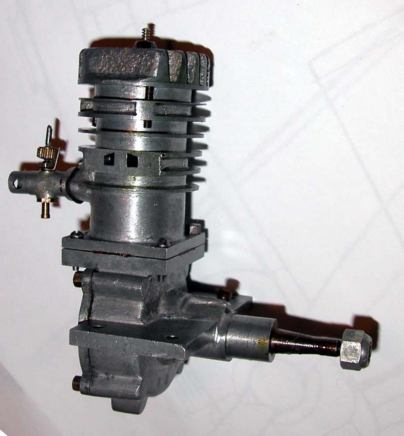
 Canadian reader, Jack Humphreys, has been breaking open boxes sealed for the past forty years and discovering mystery after mystery. This one he believes may have originated in the UK. This first picture shows it's most distinguishing feature: namely how the unknown designer expected it to breathe through a cloud of its own efflux. The timer appears to be of the automotive type, but carries no apparent markings which may provide a clue as to the country of origin.
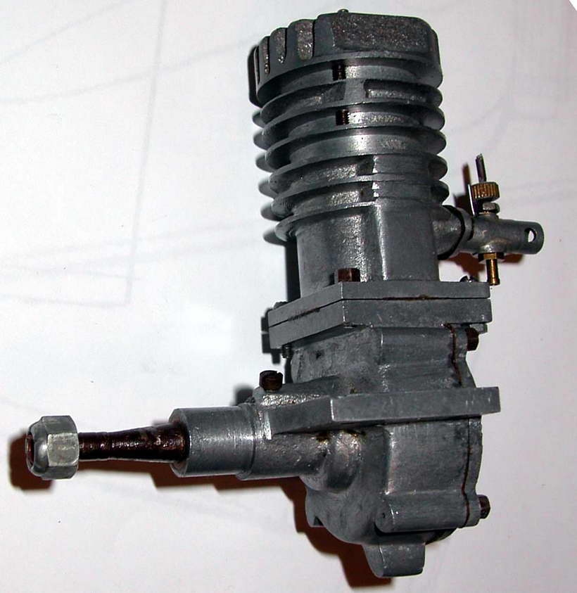
 The front shows the bypass cover and a rather astounding length of threaded crankshaft. The prop driver carries a peg guaranteed to destroy said prop in any sudden ground contact by splitting the hub—inevitably a hand carved item in the days this design probably harks back to. The rather tiny diameter driver is also pinned to the crankshaft—another idea of dubious worth considering how this weakens the shaft.
 Issues of dubious design aside, this is a nicely made engine. The die castings are very clean and rather intricate, comprising front and rear crankcase halves, cylinder, timer frame, and two cover plates. A lot of work to go to for a one-off, so do more exist? We are not 100% certain of the origin and don't know the screw threads used. The type of fastners used are often a dead give-away as to the origin: NC/NF in the USA, BA in England, and metric on the Continent. If the threads are not known, try the head shape. These look distinctly "Fillister" shaped to me which suggests US origins as the UK "cheese heads" are generally flat topped. Any information anyone can provide gratefully accepted, and acknowledged.
Rising Sun Sparkie

 Here's another venerable sparkie that arrived for identification. It's a rather conventional sideport design with a nicely die-cast crankcase and timer assembly. The cylinder is a turned and brazed assembly with a blind bore. Many think that this complicates construction as you can't stroke the lap all the way through the bore, resulting in a less than perfectly regular finish at the very top. This is so, but remember that model spark ignition engines have a rather low compression ratio, so the piston gets nowhere near the top of the cylinder. And cross-flow engines typically have a baffle on top of the piston, so the lapping problem is not as critical as it may at first seem.

 It's the next two photos that give the clues. These are the three characters stamped on the bypass cover, which are repeated as die engravings on the backplate, plus the flag emblem stamped on the bypass. If you know your early Japanese engines, this will be all you need. If not, click the button below to uncover the answer.
The Answer:
 Our engine, identified by Alan Strutt (England), is an example of the KD 10cc made by The Great Japan Miniature Aeroplane Co Ltd of Yokohama. The term 'K' referred to the class for which the engine was eligible in Japanese modelling competitions. The displacement is roughly 9.6 cc and therefore met the prevailing regulations for a Class K engine. The engine depicted has a die-cast crankcase (as opposed to sand cast) and is thus a Type 2. Accordingly, it was probably made towards the later end of the manufacturer’s existence (before and during WW2) with the KD and KE models being the last ones produced by the company. We are told that the inscription on the rear cover translates roughly to "After the style of Inoue", referring to the engine’s designer, a certain Maseo Inoue.