WATZIT?!
Model Engines of Unknown Origin
Page 3
Last update: Nov 30, 2005
Click on images to view them in larger size and more detail.
A Big Scary Watzit
This is a very nice looking item. It's a two blade prop with a diameter of 20", featuring adjustable pitch and replaceable blades. We can't see how those blades are retained. Presumably some sort of recess is involved, but given the way the grain would run inboard of that groove, I really would not like to be around when it's turning at speed, especially to the side of it!

|

|

|
German 10cc Sleeve-valve
These photos came from Dietmar Kolb in Germany. He has no information on the engine and reports that it has a 25mm stroke with a 20mm bore for a capacity of around 10cc (9.8 actually). The carburettor is missing and he has been told that it is a pre-WW I "Drone" engine. Have a close look at the photos before reading my observations below--remember I could be completely wrong (it has happened once before  ).
).

|
|
First off, it's obviously a sleeve valve design, but then the heading gave that away, didn't it? Next, the cam that actuates timer points seem to be attached to the crankshaft, so the plug will fire on every stroke, but the gears that drive the sleeve valve appear to be the expected 2:1 for standard four-stroke operation. No harm done firing the plug during exhaust, but no point either (sorry for the pun).
The angled screws on the conrod big-end are unusual too. They would increase the volume occupied by the rotating rod over what it would have been had they been vertical. There would appear to be plenty of room in the case, so one wonders why?
There are two rings on the piston and possibly one on the "junk" head. We can't see if there is a sleeve ring in the cylinder. The spark plug looks to be a commercial item and relative to the bore, would appear to be a miniature one--possibly 10mm. As far as I know, sleeve valves did not appear until shortly after WW I (with a lot of early experiments being done by Harry Ricardo in the early 1920's), and commercial miniature spark plugs were later again--say the mid 30's. Finally, the point assembly looks distinctly modern automotive. All of which strongly argues to me that the "pre-WW I drone" conjecture is highly unlikely.
The engine appears to be very nicely made. The mounting indicates a "stationary" application, or more likely, that this was an experimental engine. Also note that the lack of any thread on the shaft indicating that some collet system was probably used to retain a flywheel (common practice with model boats allowing it to slip if the engine stopped suddenly due to a dunking, thus preventing damage). There is no indication visible of where the carburettor attaches, but it would have to be somewhere on the ring around the middle of the cylinder which must double as the inlet and exhaust manifold somehow. If anyone has information about this engine, we'd appreciate hearing from you--and so would Dietmar!
Unfinished Hungarian Watzit
Another one from Bert Streigler (he's just floating in Watzits!):

|

|
This came my way from Jim Dunkin and he got it along with a collection of hungarian diesels, so it was assumed to be a Hungarian engine. It is unusual in many ways in that it is a .46 cu. In. displacement with a fairly square bore and stroke, but the rod is very long and the cylinder is much taller than it needed to be. The bypass cover stands about .030 proud of the rest of the cylinder, which was laboriously (and beautifully) all milled away to allow this to be, all with a mill about 1/8" in diameter!

|

|
The head appears to have been a die casting that was cleaned up on all surfaces. I am guessing from it's shape that it was off of a Feldgibel (sp?) engine of German origin, but cannot be sure. The massive 8mm crankshaft is threaded 0.5mm! (yes, 0.5mm!). All the machine work is first class, right down to the cast magnesium crankcase - not a task for the faint-hearted.
It is entirely possible that this was German rather than Hungarian, but I just do not know. It was never quite finished as the timer is incomplete. It would have been nearly impossible to mount the thing with the way the mounts were made and the holes were placed.
Maybe someone out there knows what this thing was?
YAMS (Yet Another Mystery Sparkie)
 Photo 1
|
 Photo 2
|

Photo 3 |
The Cylinder (apparently a blind bore; not having handled it, we can't really say) is nicely made and brazed, but the soft solder work on the spraybar and choke shutter are of a different, significantly lower class. This may indicate later repairs by a different individual.
Mounting would be tricky as the case screws would appear to be meant to act as studs, but are rather short--and the bosses for the rear cylinder hold-down screws are rather in the way too. My guess is that the builder most likely intended to use Calkin Elf-style steel frames.
That's all we have to go on. No dimensions; my guess would be in the .60 range for displacement (made popular by the Browns). If anyone has seen something like this before, Model Engine News would love to hear about it.
Who Made This RTF?

That's not a lot of real info to go on. I know that R/C drones were made in the US during WWII for gunnery practice, but this is not one of them (they were large and surprisingly sophisticated). And there's a big difference between R/C and C/L! The idea of standing in the middle of the circle while a bunch of recruits take pot-shots at the model does not bear thinking about. Next mystery is the RAF-like fin flash and roundel on the wing, plus an RAAF-like serial number on the fuselage. Bunch is American! But the wheels look like Trixler balloon inflatables which would be correct for the period. If anyone can shed any light on the model we'd be most appreciative.
An Embryonic Opposed Twin

 Photo 1
|
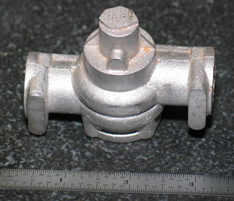 Photo 2
|

Photo 3 |

Photo 4 |

Photo 5 |

Photo 6 |

Photo 7 |

Photo 8 |

Photo 9 |

Photo 10 |

Photo 11 |

Photo 12 |
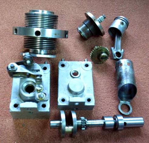
- Photos 1 through 4 show the crankcase. It's green-sand cast, but quite nicely cored which argues that the pattern maker was an accomplished foundryman. The twin bulges concentric with the case are just like the Wasp Twin circa 1946. They provide clearance for the conrod big-end straps and screws. But unlike, the Wasp, the crankcase if not designed to be split longitudinally to facilitate assembly. This means that the big-end strap screws are going to have to be inserted down the cylinder bores after the crankshaft is inserted, but before the pistons are attached. Quite a tedious operation, I'd guess. Photo 4 clearly shows the fore-aft offset of the cylinder axes, designed to place the conrod on the centerlines of the cylinders of the two throw crankshaft (quite conventional).
- To complete assembling the engine, either the conrod wrist pin hole must clear the case casting with the crank at TDC, thus allowing the piston to be attached after the rods have been assembled, or a hole must be drilled in the case to allow the pin to be inserted through the case. The hole would later be effectively closed off by insertion of the cylinder liner (Super Tiger used this design feature on their ST60 cross-flow series that was such a great C/L stunt engine).
- In photo 2, at the front, note the three webs strengthening the main crank journal. These would prevent attachment of a timer, arguing that the engine was intended for glow-plug operation. The larger pad cast into the front is, I believe, intended to be blind-drilled and tapped as the front mounting point (more on this later). While the approximate cylinder bores are cored, the bypass bulges do not appear to be (I could be wrong, but see also the partially machined case in the heading photo). So additional machining will be required to hollow out the transfer. This could be done from the cylinder seat after boring for the cylinders, though it would probably need a "long series" end-mill.
- In photos 3 and 4, the "belt" around the exhaust stack area appears intended to carry the screws that will hold down the head and finned cylinder liners (like a McCoy Red-head, or K&B Green-head). The cored bore looks like it would clean out for a cylinder with a bore of about 0.7", or a bit larger. Assuming a "square" design, this would give the engine a total capacity in the vicinity of 0.60 cuin--just like the Wasp, and other similar designs.
- Returning to photo 2, it's possible that the case was intended to have a single ball-race at the front--judging from the extra metal ahead of the front cylinder. The rest of the shaft, front and rear, would run in a rather thin bronze, or cast-iron bushes.
- Photos 5 and 6 are obviously the backplate, venturi, and rear-mounting feet. Note from the slightly high-set location of the feet, how they would align with the pad at the front of the engine to provide a three-point mounting system--most unusual, unique even. The venturi would feed a rotary inlet valve drilled into the rear portion of the crankshaft--again like the Wasp. And like the Wasp, the front cylinder, being further away from the inlet, would run leaner than the rear-most cylinder. Other designs (like the DC twin) overcame this by having rotary valves in both front and rear parts of the crankshaft. The later Super-Wasp placed the two cylinder axes in the same plane, requiring the conrods to be offset from the cylinder axes, thus swapping one problem for another (the Ross 2, 4 and 6 cylinder engines also did this, to no apparent detriment).
- In photos 7 and 8, we see the two throw crank. The webs are about 1" diameter. With 1/4" crankpins, the throw would be about 0.7", supporting the theory that the design was roughly square, of .60 cuin total capacity, or a bit over. The builder appears to have cut the offset crankpins first, then soldered bracing pieces into the gaps to support the shaft against compression loads as the main journals were turned between centers. The inlet hole and passage have yet to be drilled. This hole would be drilled from the rear, requiring that it either be plugged, or that the corresponding bearing hole in the backplate be plugged. The center web would either be centrally drilled to feed the front pot, or the sides of the center web milled away (see the Wasp cut-away drawing). Finally, the soldered in slugs would be removed.
- Photos 9 and 10 are a complete mystery. I suspect the rod with the odd longitudinal protrusions has nothing whatever to do with the twin, but I'm open to suggestions. Equally as mysterious is the odd gizmo shown in photos 11 and 12. At first, I thought it was the ignition timer body, but the webs on the front of the crankcase strongly argue against this. One wild suggestion has the engine intended for use as an "outboard" motor with the long casting containing the drive to the submerged props--to which I say the honourable gentleman in question has been hitting the good Australian cab-sav a bit harder than normal!

There you have it. My guess is that is was a home design and no plans exist, 'though for the owner's sake, I hope not. If by any strange chance you can shed some light on this design, we'd all be most grateful, and if you can provide plans, there's a casting set in it for you. Send suggestions to me at this web site.
A Tough One

 intersect like a crossword puzzle on the "A". The GAN is horizontal and the FAN, vertical.
That may be enough to give you the probable genesis of the twin.
We can see that it's water-cooled, quite large, and we have good reason th suspect it may have been intended for marine work.
intersect like a crossword puzzle on the "A". The GAN is horizontal and the FAN, vertical.
That may be enough to give you the probable genesis of the twin.
We can see that it's water-cooled, quite large, and we have good reason th suspect it may have been intended for marine work.
A Good Little Socialist Diesel

This nicely made little diesel (2.5 cc capacity) we believe to be possibly of East German origin. Bert thinks it may be an Elgin, but he is not at all sure. Another suggestion was that it may be an Alag, but all of those that I've seen have a bakerlite or similar early composite material backplate. In some ways it's like a Yin-Yan (check the similarities around the cylinder liner exhaust ports, venturi insert, prop driver, comp screw and general crankcase design), but the Chinese were good at engraving their dies and this one is clean, so we didn't think it's one of those either. Then Bert put it side by side with his Yin-Yan and as he said, the plot thickened:

Now the plot thickens on the ID of the blue-head "socialist diesel". Both engines have a 15mm bore and both cases have the same deck height. My original Chinese Yin-Yan on the right has much superior crankcase castings, thinner cylinder and slightly different exhaust port flanges. The crankcase backplate on mine is recessed .400, while the blue engine is recessed .480. The cylinder muffs are not interchangeable because of the thread diameter on the thicker cylinder of the blue engine. I know the Yin-Yan and the Alag were made from the same drawings, but with minor styling changes, and a version was made in Germany by Engel, again with styling changes.
Comparison of the two might not be fair simply because my Yin-Yan was one of the first (if not THE first) to ever hit these shores. A friend in Military Intelligence got it in Hong Kong for me on one of his diplomatic trips and was told they were something very new. The instructions with it were in sorta-English, and state that "This is engine we have made for you and is the engine you will use." I suspect that was directed at the locals over there. It hardly fits the western style of free choice. Serial on my engine is 0244. This engine is superbly made inside and out and has a fully machined alloy rod. The cylinder is turned to a very high external finish and internal fits are perfect. The blue engine is also well made. It has a serial number of 1O59 (that is an O, not a zero)on the underside of one lug, and 79 under the other lug. The rod in this one is a square section rod, also machined from the solid, but roughly finished. The quality of the casting is not nearly so good in appearance. The bearing webs are much thicker and there is only a rudimentary web on the intake. The bottom of the case is about .080 longer, which explains the .080 deeper backplate. None of this precludes it from being a later model of the Yin-Yan.
So, there you have it. The blue engine is definitely taken from the "socialist diesel" design, but the question remains, "who made it?"
Still with us? This mystery has been with us for several days now and you are reading a blow-by-blow, edited description. The next link towards positive identification comes from Jim Duncan:


Hi all. I have been digging in my stuff and found a little more about the mystery engine. In spite of it's similarity, I don't think it is a Silver Swallow, Yin-Yan or whatever. I think the name of it is "T.Y.C." whatever that stands for. I have found out that it was made in Chongqing, China. My example was made in 1984 and has serial #1084. I suspect that, while it might be a different factory, there must be some connection with other mfg's. There was a certificate for the engine issued by the Three Leaves company. The Three Leaves (S.Y.) company is located in Shen Zhen City, China. The Yin-Yan's were all made in Shanghai.
I have attached copies of some paperwork from the TYC (including the "certificate", the box top for the TYC and paperwork for the SY engines. I have sent a photo to Mr. Gao Guo Jun of CS engines to see if he can help with information. He took over the Yin-Yan line of engines after they folded. I will also show the paperwork to my daughter-in-law (who is Taiwanese) and our son who speaks Mandarin Chinese and can probably read some. I will see if any of it is useful information. More as I find it out.