Building the Taplin Twin Prototype Replica.
Last update: Sep 25, 2000

This engine holds a special fascination for me that dates back to the mid 1950's. The Taplin Twin was one of those engines appearing in monthly Aeromodeller adds with an astronomical price tag that as a school boy, I could only dream about. By the time I could afford one, Taplin had ceased manufacture, although production did restart in India some time later (for the full Taplin story, refer to MEW, issues 31..xx). Before going into full production Colonol Taplin ("Taps") produces some prototypes using a horizontally split cankcase, much like full size engine practice. When reproductions of this casting became available through Barton Model Products in the UK, I quickly ordered a set and placed them "under the bench" for a rainy day. Now, that rainy day is here.
I don't plan to write volumes about this project, as the engine has already been the subject of a series of articles by Mike Crisp in Model Engine World. However, I will highlight a few key aspects where my observations may be of value to builders of this engine, or builders of engines employing similar features.

The cylinders used on the prototype engine were adapted from standard ED "Competition Special" units. As these locate in the crankcase with a 1/16" spiggot below the mounting flange, they should be made before the crankcase can be machined. The MEW engine used actual ED Comp. Special cylinders. These engines are like hen's teeth in Oz and in addition, I question the morality of carving up a collectable engine to build a replica. So, using a run-out "bones" engine kindly provided by the Empire Motor Boy (Ken Croft), I made a pair of cylinders. This shot shows the cylinder being bored. All my long narrow bores end up tapering to some degree. I suspect this is due to springback in the tool. I'd have prefered to bore from the flange end so the taper is in the right direction, but this would have complicated turning the upper cylinder and its thread, so I just accept that a lot of carefull lapping will be needed.

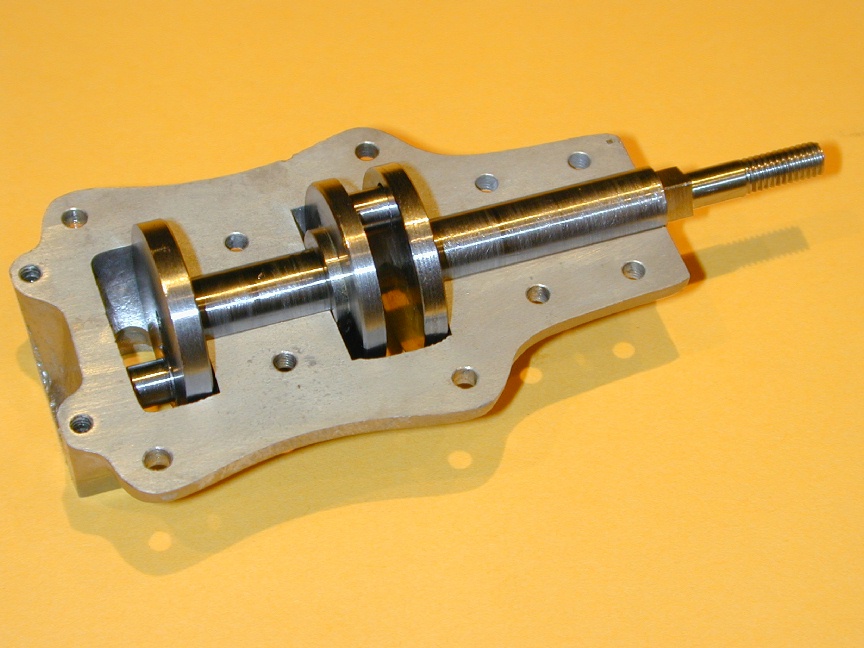
The split crankcase castings will mate with no locating pins, nor gasket so their flange faces must be as close to perfectly flat as possible. After agonizing over this for some time, I decided to use my little 7" shaper (a renegade from a US battleship). This would give outstanding flatness, provided my work clamping did not introduce any spring into the part. This shot shows the lower half clamped and nearly done. The upper half rests beside it for comparison. Subsequent bluing of the parts shows them to be flat. So far, so good. (Note that only the mating flanges are machined at this stage. The cylinder mounting flanges remain as cast).

At this point I discovered what I believe to have been a major blunder on the part of the pattern maker. The flanges, according to the MEW construction drawings, should be machined down to 1/8" thick. No problem, especially with the shaper, although setting them up required lots of measuring and gentle tapping to achieve uniform flange thickness. The castings had a generous allowance on the flanges of over 1/32". The pattern maker allowed for a channel that will be opened out to carry the crankshafts, but must have made this using half-round stock, so after the flange is machined down, the channel looks like a flattened elipse. This will be an absolute nightmare to bore true for the shaft. Damn, damn, damn, damn! If only the channel had been omitted, boring though solid ally along the parting like would have been very simple. *sigh*.

The MEW articles made a rather complicated jig that mounts the case on the cylinder flange. Subsequent operations are complicated by this setup. The Ladybird in-line twin designed by Edgar Westbury used a similar split case arrangement, but with a conventional two throw crankshaft and split big ends on the con rods (Taps would later be granted a patent for his way of avoiding these split big ends). In his construction series that appeared during the 1940's in Model Engineer, Westbury made a simple "U" shaped jig to mount the engine by its mounting lugs. As this base was carefully squared, it formed the reference surfaces for subsequent machining, then doubled as a display base. I decided to emulate this, so the mill and shaper were used to make an aluminum base. In this shot, the case halves are clamped into the base so the mounting holes can be drilled through both case segments and into the base in one operation (the base is hidden in the mill vice jaws). The bottom of the mounting lugs have been milled flat (clamping the casting to the mill table on its flat upper surface) and the channel of the "U" machined perfectly parallel to one (reference) side of the base so the lower case half is a zero-slop fit in the channel.

With the case halves now firmly mated by the socket head mounting screws and the base flat on parallels in the machine vice, the six holes for the upper case clamping screws are drilled thru for tapping 6BA (roughly 4-40 in UNC terms). The hole is opened out to clear 6BA in the upper case half, then tapped. The tap is initially placed in the drill chuck and rotated a few turns by hand to ensure it starts vertical. The chuck is then loosened and replaced by a small, sensitive tap handle to complete the job. Finally, the casting is spot faced at each location for the 6BA cheese head screws that secure the segments. With this complete, the top is fly-cut to height.

After locating the median center line of the cylinder mounting faces, the holes to take the cylinders are counterbored undersize with a slot drill, then brought to a close fit on the finished cylinders. The cylinders are marked "Forward" and "Aft" to ensure best possible fits in these holes. Although difficult to make out in this out-of-focus shot, I'm adjusting the boring head using a dial test indicator held in a magnetic base against the tip of the tool. This is much more accurate than the calibrations on the head which I suspect are metric anyway!

The con-rod clearance slot is then machined with a 1/4" slot drill and the eight cylinder attach holes are blind drilled and tapped 6BA. I tend to do these operations to co-ordinates using the digital read-outs on my mill, rather than the time honored "spot" through the holes. Seems risky, but it works for me as long as I can pick up a good reference point. Blind drilling ensures no possible crankcase pressure leaks, even though it complicates the tapping process.

The case is now removed from the base and clamped upside down to blind drill and tap the rear case securing holes. All in all, that case has 16 holes drilled and tapped 6BA (roughly 4-40 equivalent). Of these, 10 are blind. The base adds another four blind tapped holes. Rather a stressfull operation and my tap was feeling decidely blunt by the end of it, or maybe it was me! Note the ubiquitous business card under the case. This protects the cylinder seat and provides a bit more friction when clamping.

This shot shows "The Challenge" awaiting - which will be to drill and bore/ream the blind hole for the crankshafts into an irregular shaped hole. This will be a real test of ingenuity as that hole is absolutely guarenteed to lead any twist dill off the straight and narrow. If that happens, the shaft will not be perfectly at right angles to the cylinder bores and so, friction will go through the roof. I really wish the pattern maker had not tried to be so helpfull. I also have a nasty feeling that the cavities for the crank webs will be too small as well and fixing that will extremely tedious. I could measure it now, but I'd rather not know just yet.

Here the project starts to take shape. From photos of one of the original Taplin prototypes appearing in Model Aircraft of July, 1955 and Clanford's Index, it is apparent that the cooling fins were not stock ED Comp. Special units. Rather, each had an additional pair of fins, so that is what I've made for my replica. The article also shows the engine disassembled. This is most interesting as it definitely shows the crankshaft(s) ran un-bushed. The MEW replica goes to considerable agony to make a split rear shaft bushing and pound the cast iron bushings out of some poor Comp Special for the front shaft. Perhaps this was due to inspection of yet another prototype that was bushed. For simplicity, I'll go unbushed with mine.

Getting ready to join up the cylinders now. Here is the way I have settled on for making bypass covers of the ED/Sparey type. First, an aluminum male form block is filed to shape. Then a shim of thin steel (about 10 thou) is cut and slit at one end. This is clamped to the form block and the cover gently tapped to shape using assorted dollies. This shot shows a before and after look. Naturally cutting the slots with snips causes deformation which must be tapped flat before the part can be formed. Note the very close fit of the turned down part between the sides.

Next, the formed end is silver brazed on the inside. The outside is then trimmed to shape, following by filing and buffing. As can be seen here, the silver braze becomes invisible and it looks like the part has been stamped to shape.
 This inside shot shows the silver braze. The covers will be soldered to the cylinders with high temperatore (soft) silver solder. As the melting point of the braze is much, much higher than that for the soft solder, the integrity of the cover will be maintained. Note that the cover on the right here has been carefully shaped to match the cylinder contour. next, soft soldering and burnt fingers.

In soldering up this unit, the secret is to tin all the mating parts first, getting good coverage and solder flow, wiping off all the excess solder with a rag while the solder is still molten so that only the hint of the tinning remains. The parts can then be jigged up (using the actual crankcase) and soldered together with minimum fuss as we are simply melting the existing tinned areas into each other. In olden days this was a common practice called "sweating". I use a propane gas tourch for jobs like this, along with an old scriber tip that I drag around the joint like an old fashioned, externally heated soldering iron. The scriber tip is well tinned and allows me to control the amount of solder in the fillet a little better than trusting to chance and a following wind.

It's a dirty job, but someone has to do it. The lap here is from aluminum, impregnated with diamond paste (red grade). After a lot of lapping, I've reversed the taper in the bore and hopefully, not bell-mouthed anything too much in the process. One thing about lapping a uint like this, the extra cylinder makes a neat handle to grip the cylinder being lapped! The bore is a nominal 0.500" and I'm aiming at a taper of under 0.001". A little bell-mouthing at the bottom does not matter. Nor, surprisingly does it it the top, provided you make the contra-piston using David Owen's method.

Next cones the rods. The are made from "gauge plate" which is a high carbon steel that can be harneded and tempered. As usual, we start by drilling and reaming the holes in a piece of plate stick sitting on parallels in the milling vice. Next, the blanks are rough sawn and sat on edge between the mill vice jaws with carefully selected rods through their holes to rough profile the taper and finish the ends to be symetrical around the hole axis. The exact centers of each face are then located and small centerdrill points made so the rods can be taper turned between centers. In this shot, we get a before and after view.

Now over to a small roraty table under the mill to profile the ends. This leaves a small pointy pip either side of the central rod that I've fared into the end using a small grinding stone held in a Dremal tool (a chain-saw sharpening stone, actually). If you look closely, you can see grinding marks still present on the rods. Thes will be carefully removed with needle files and fine wet 'n dry paper before hardening and tempering.

With the bores lapped, the pistons can be made and honed as individual fits (no point trying for interchangability). I've been convinced by David Owen and Stan Pilgrim that aiming to remove minimal metal in the piston honing phase is a good thing. The theory being that the less metal removed, the more cylindrical the piston remains - not to mention the savings in effort and lapping oil! This shot shows the point at which the pistons stop sliding into the bores before starting the honing process. Note also the light chamfer on the piston skirt. Experts like Bert Striegler who know a lot about lubrication tell me sharp edges break down the working oil film from the cylinder wall.
Note to self: Don't do this again!. I did not leave myself anywhere near enough metal to hone the pistons. At this stage, both still have machining marks in them and both are a worn out fit in the cylinder. I'll have to make new ones, or try "growing" the cast iron. All too difficult for now. I'll defer the decision until they are moving up and down mechanically.

Electronic Developments Ltd had some strange (to me, at least) notions regarding contra piston design. Specifically, the top of the contra piston protrudes above the top of the cylinder in the normal running position on several of their engines; namely the Penny-Slot, Competition Special, Baby and Hornet. This is understandable for the "Penny-Slot" as the actual screw-on cooling muff also formed the compression adjustment method, so the contra piston needed to protrude. In the others, this arrangement needlessly complicates the interior of the cooling muff. For example, on the Comp. Special head, this requires that a narrow channel is rebated into the ceiling of the muff so that: (a) The outer diameter of the ceiling can seat against the cylinder allowing the cylinder to be tightened up, while (b) a central "post" gives extra threaded material to support the compression screw. Now, why am I going on about this? This shot shows my finished contra pistons made, as mentioned previously, using the DCO Method. This gives very thin walls with a one (1) degree included angle taper so they can compress to form a gas tight, yet still be an easily adjustable press fit into the cylinder. I've made them to the height of the original design, but I think they could easily have been made 3mm shorter.
If you look very closely at the top of the cylinder bores in the picture, you can probably see a slight demarkation line between the lapped cylinder bore and the degree of bell-mouthing caused by a less than razor sharp tool used to bore the cylinders (remember, I had to bore from the top down because I wanted the mounting flange to be closest to the chucking stub in order to simplify turning and threading the cylinder). I could have parted off before boring, reversed the cylinder, then bored from the bottom; finally facing the flange so it would be normal to the bore, but this would mean I was gripping the cylinder by its thin walls (part of which are threaded) and that just did not feel right.


Now to the difficult job - achieving a bore for the crankshaft that stays on line with the crankcase split line and in line with the plane formed by the cylinder center lines. All this while an irregular shaped and non-aligned cavity attempts to pervert the process! The first photo shows the crankcase, mounted to an angle plate, being aligned with a face plate. This achieves the correct orientation of the bore. Now it has to be brought to the lathe axis. To do this, the end of the irregular hole has been plugged with an aluminum slug locktit'ed into the end and center popped. Next a plunger DTI and tailstock supported wobbler are used until the work is rotates with less than 0.0005" wobble. That completes setup. Now for the white knuckle part.
First, the plug was center drilled, slot drilled and bored .281" for about 1/4" deep to support a 9/32" D bit reamer. It was hoped that as a single point, unfluted drill, the D bit would stay on track irrespective of the shape of the cavity it was passing through. Thankfully, this worked, although the bit had to be withdrawn every 1/16" inch of progress to clear the chips. Next, a 5/16" chucking reamer was passed down the bore to produce the final hole. That was a complete disaster. The long and short of it is: I ran the reamer too fast; chips galled the bore (the cast material is quite soft) and now have to make the hole larger. If I can get some 11/32", or 8.5mm drill rod, I'll make another D bit reamer, than make larger diameter crankshafts to suit. If not, it will have to go to 3/8 and at that point, I may as well go out to 7/16" and bush the shafts. Nobody said life would be easy.


How's this for airing your dirty laundry? The first shot here shows the lamentable state of play following the reaming failure. After a lot of effort, I managed to obtain some 11/32" drill rod (many thanks to Eric Offen in the UK) - would you believe that after 5/16", the Australian agent does not import drill rod in anything but 1/16" steps!!? Enough to make me think I don't live in a first world country. 8.5mm would have been acceptable as well, but not even that is available. Anyway, with Eric's help, an 11/32" D bit was made and the case went back in the jig. This time I ran the D bit at 75rpm with lots of kerosene. The result is "acceptable". If you look closely at the photo on the right, you can see some minor scoring at the aft end of the front and rear journals where I was having difficulty getting lubricant in. Makes me wish I'd just used D bits in the first place and saved myself the expense of the chucking reamer I'll probably never use again.
Perhaps if I'd thought to heat treat the case, these operations may have gone better. Too late now though. If you look even more closly, you'll see that the thrust and bearing faces of the crank web cavities have been faced. And looking closely, you will see that the facing has broken into the bottom of the rear screw holes for the front cylinder (bugger). Now look even more closely at the same face in the lower case half. That face has not even completely cleaned up. Yet another minor problem in the pattern.
Again, I've departed from the drawings published in MEW which show a "normal" front shaft (ie, one with a pin) and a rear spool with a hole in the forward web for said front shaft pin. The photos in the 1955 Model Aircraft show the spool having two pins and that's the way I decided to go. First, I made carefull measurements of the internal dimensions to find out how my case hade machined up and laid this out in TurboCAD. Next I drew the shafts with the 0.115" thick crank webs and added thrust faces whose thickness was adjusted to make the conrods fall in the center of the cylinder locations with about 0.010" free play.

The front shaft was made first. This was a simple turning job (no pin!) with the shaft being honed to a free running fit in the case using my little Sunen clone hone. Next, how to make the "spool"? As the pins would be turned in a Keasting plate, the OD of the webs needed to be perfectly concentric with the shaft area to ensure the pins are in correct axial alignment. To do this, I sat an oversize blank of the correct final length on a V block on a surface plate and accurately scribed the diameters on the ends. Then, with the lathe chuck on the trusty rotary table under the mill (accurately centered), I center drilled the axis and two offset crankpin locations. At this same setting, the hole in the front crank web was drilled undersize, then finished with a slot drill. As a precaution, the hole was converted to a mild, radial slot to allow for 0.010" of misalignment.

The shaft center and webs were then turned between centers with a lathe dog attached to the "long" pin portion of the blank. This allowed the partially finished part to be easily removed from the lathe for trial fitting in the case, then returned to the lathe for additional finishing. The shaft area was finished with a piece of 600 grit wet 'n dry and liberal oil, backed up with a piece if 3/8" sq HSS tooling. I could not spin the spool in the closed case as there was no way to get at it, but when I could easily shake it back and forth, I figured it was probably done. This was a nervous moment, as when the pins were turned in the next step, the centers used for turning the shaft area would disapear. However, it all worked to plan and both shafts rotate freely as a unit in the tightly bolted up case.

This shot shows an original and well used ED Cometition Special spinner on the right, with my reproduction on the left. The inside was milled out first using 1/8" and 3/16" ball end mills and the rotary table. The center post was then drilled and tapped 2BA. Next, the tommy bar hole was drilled 5/32" and the blank cut to length. To profile, it was screwed to a 2BA stud on a mandrel and angle cuts at 15, 30 and 45 degrees taken to get it "close" to a template cut to fit the profile of the original. This template was reproduced on a piece of soft, high carbon steel plate 1/16" thick. The plate was then fully hardened. The edge of the profile was finished and a relief of maybe 5 degrees ground in with a Dremel hand tool. Finally the top of the form tool was stoned to give a cutting edge.

In use, the tool is gently rocked back and forth with the saddle while the cross slide is moved in and out. The intent is to only have the tool contacting the high spots, rather than operating over a broad area. The process is hard to describe, but easy to do. Depending on the finish on the form tool, the result can either be the finished product, or it can be polished further. I was not happy, so went with fine grade glass paper and kerosene applied with a finger, followed by Brasso polish. The prop driver visible in this shot is also a repro of an original. Rather than serrations, it has eight pointed pips. These I reproduced with a D bit form tool. I'm not super-pleased with the result (hence no photo  )
)

Both prototype and production Taplins drew heavily on the ED parts bins. Along with cylinder, pistons and rods, the prototype used the prop driver, spinner and needle valve assembly from the ED Competition Special. The NVA comprised a cast aluminum body with a knurled brass knob into which was pressed a steel needle that I rather suspect had its origins in the gramaphone industry.
While I'd intended that the carburator body be my foray into the foundry business, impatience to finish the engine got the better of me. The result pictured here was fabricated from 3/8" and 5/16" aluminum stock, the former cross-drilled to accept the latter and held together with Lok-tite (tm). As the horizontal part would be very weak after cross-drilling, it was drilled and tapped 0BA first. Similarly, the vertical protion was finished to profile, drilled and tapped 6BA (close to 4-40) at one end and blind drilled 1/16" the other. After gluing together, the venturi hole was drilled #30, then tapered internally and externally on the inlet side. Finally, the jet hole was drilled #60 to break into the 1/16" hole. In retrospect, this operation should have been done while drilling and tapping. The needle carrier was a simple brass knurling and turning operation. My needle is from 0.055" music wire, ground off-hand and glued into the carrier. My knurl is probably a bit course, but never mind.
After carrying the thing around the house with me for a day to admire it, and showing it off at the local C/L field, I decided to try an expirement on the pistons before making completely new ones. Fellow Motor Boy George Aldrich knows a LOT about speed engines and tells me he "grows" cast iron pistons a couple of thou by heating to red heat and oil quenching. On the theory that this pair was stuffed anyway, I gave it a try on the worst one (the front). "Before" measurements gave a diameter of 0.5044". The piston, held on a piece of soft iron wire was brought at a bright orange in a propane tourch and quenched in chain saw oil. The "After" dimension measured 0.5060" with no appreciable out of roundness. A little honing soon removed the scale and produced a good fit in the front cylinder. The piston is still not as polished as I'd like indicating just how under size I'd turned it (and how blunt the tool had been). Reassembled, the front pot would now "pop" on a prime. With this encouragement, the back piston got the same treatment with similar results: growth of 0.0016" and no distortion. Simply amazing. With both pots a-poppin, I just had to try for a run.

My haste for this acid test is evident in the tank lash-up (ok, not that different from any other of my tank lash-ups you say?) The engine was fitted with a Zinger 13x6 wood prop to get a good flywheel and with camera and tach standing by, I stareted flipping, and flipping and... I was getting pops and occasional bursts, but nothing to write home about, so time to resort to science.

I backed off the compression on the front pot and worked on the rear to the point where it popped nicely, then started advancing comp on the front one. In no time, the beast was actually running! A little adjustment on the comp screws and needle had it sounding great with a tach reading of 2500 rpm. Hmmmm. Bit slow, but then it's swinging a big prop. There was a lot of goop coming out, but it was relatively clean goop and diesels are dirty beasts. Some quick shots for prosterity and now for another check on rpm. At this time, the tank started to run dry and the steady thump changed to a frightening scream like demented banshee. The rpm leapt up to 4900 and stayed there as the Taplin Proto sucked the dregs from the tank. A quick refuel, a prime and a couple of flips and it was running again. Finding the magic compression setting appears to be the trick. I let this run proceed at a sedate 2500 rpm as before and again tached twice that as it leaned out at the end of the tank. Very encouraging and very noisy.
I'm calling the Taplin Prototype Project complete and a resounding success. I've plans for a nice little brass tank on milled aluminum struts out the back of the display stand and if that gets done, this article will get an addendum. I also have to wind a reproduction spring for the needle valve. The one pictured earlier is an original and must go back to her owner (Motor Boy Ken Croft in the UK). I'll give the engine some more running in and try some different props. This will be done at flying fields (1) so others can enjoy seeing an historic replica doing its thing, and (2) because at full bore, the beast is just too noisy for residential areas!

 Home
Home
This page designed to look best when using anything but IE!
Please submit all questions and comments to
enquiries@modelenginenews.org