 |
Westbury Whippet Project:
|
The Whippet has now reached what I term the fettlin' and fiddlin' stage. This is not quite final assembly, though the fiddlin' part is necessary to achieve final assembly as some parts will need a bit of adjustment before they can be fitted. The fettlin' part of the process is the adjustment of those things that maybe don't really need it, but which make the difference between something you can have pride in, and something that is simply adequate.
 The first item that comes under the fettlin' category is the rather pedestrian match of the gearcase cover to the main casting. About the only positive thing I can say about the long-ago pattern maker is that at least the registration is fixable by removal of metal—we don't have to add any! As you can see in this photo, the raised boss on the rear of the case bears only a passing resemblance to the cover profile. While this will have no effect on how the engine runs, would you really want to show it to anyone like this?
 The first step is to scribe a line around the gearcase outline, then clamp the main casting to the mill so a nice straight line can be milled with a 1/8" ball-nose cutter along the slanting location that forms the top edge of the cover. Aligning against an engineers' square gets us close, then a sharp pointer in the mill chuck is used to check the position of the casting on the table so that movement along the Y axis tracks the scribed line. After this is milled away to touch said scribed line, the handles can be fiddled (poor man's CNC) to nibble away the bit around the screw boss. Tip: move just one handle at a time. Computers can do both, but normal people can't—even some computers can't, but they hide the fact by moving very fast. Don't try to be too precise here and be sure not to cross the scribed line.
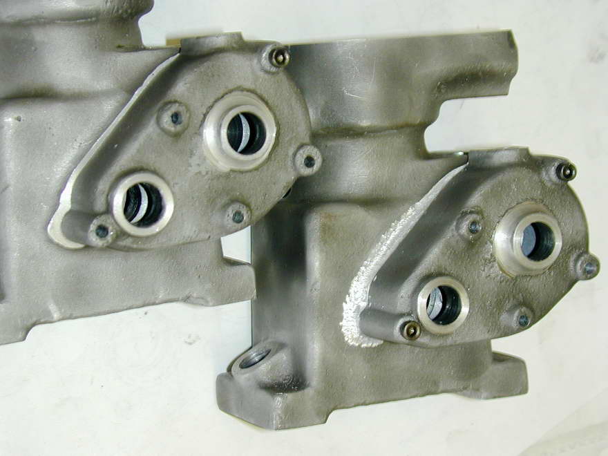 This photo is effectively a before (left) and after (right) shot, using the two cases. After the milling, a round burr in a Dremel tool has been used to smooth and blend the little steps left by the manual CNC effort. Next, a "riffler" file will be used like a scraper to smooth the tool marks left by the Dremel. To finish off, the shiny areas produced by the filing will be sand-blasted again to restore the overall finish, but we have other things to fix before then.
 To fix the protruding side of the cover, it is securely bolted to the case, gripped in the bench vise, and attacked with a very coarse, square file. The alloy is too soft to use a fine file on—even if "chalked", fine files will load-up and score the surface badly, requiring more filing, producing more scores... A coarse file, applied lightly, can produce a remarkably good finish using a process more akin to scraping than filing.
 Another area long overdue for attention is the sump drain plug. As cast, the boss is too tall and the mounting runners too short to actually fit the screw-in plug and still be able to bolt the engine to a flat surface. After some measuring and guestimation to give the thickness of the casting at the bottom of the sump, I decided that I could mill some material away to accommodate the plug without breaking through, or having so few threads engage that the tapped drain plug hole in the case would be nothing more than a stripped thread waiting to happen. This is a fiddlin' step, the alternatives being a recessed bore for the drain plug (no effective difference in threaded length), or no plug at all.
 Here we have all the castings bolted together for the final sand-blast with the areas I want to stay smooth and shiny masked off like it was being spray painted. I use a "total loss" automotive parts supply gun with an attached sand bag that does the job. A long air hose gets me away from the shop and next to the neighbour's prize geraniums. As the grit is going to go everywhere, protective attire is dust-coat, cap, gloves, face-mask complete with serious air filters, goggles, and ear-protectors. Must be quite a sight.
 This one is a bit of a chicken and egg problem for this write-up. While it definitely falls in the fiddlin' category, it requires that we progress well into the Final Assembly stage in order to discover that it has to be done! What to do? I'll cover it here and refer back when the Final Assembly section gets written. The problem is caused by the shape of the cavity cast roughly into the cylinder head. The heart shaped depression approximates the combustion chamber devised by Sir Harry Ricardo for side-valve engines, but is about as precise as the rest of the castings when it comes to shape.
 I rather suspected that this rough shape was not going to do the job, and lo! As seen here, either valve at full lift strikes the head, so some extra machining of the lobes in the cavity is required in order to provide free, unobstructed movement of the valves. This is not something you can just hack away at with your Dremel as excess clearance will decrease the compression ratio. In other words, we need to machine the valve pockets precisely where the valves will be at full lift, and nowhere else.
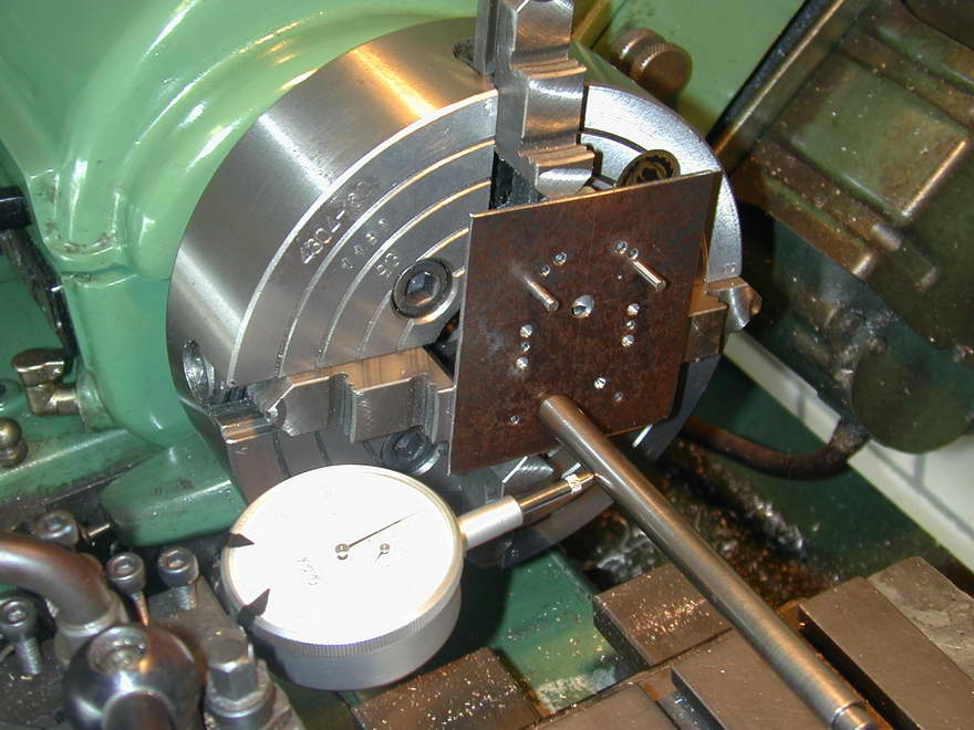 This turns out not to be all that difficult. First, we mark out and center drill the valve locations on the steel plate used as the template for the mounting and water cooling passage holes, relative to the previously established axis. The plate is then doweled to the head with 1/8" pins in the water passages, then gripped in the 4-jaw chuck, clocked so that the head turns true on a valve location. A D-bit form tool with rounded corners a bit bigger in diameter than the valve head is now mounted in the tail stock and advanced 3/16" deep into the head relative to the mounting face. After repeating for the other side, the edges are blended into the cast opening with the trusty Dremel tool and a round burr. Problem solved.

For the record, the actual proportions Sir Harry arrived at are shown in this diagram which accompanied Prof Chaddock's 1976 article in the Model Engineer on the subject of piston rings and compression ratios [1]. These numbers stack up reasonably well against those in the Westbury drawings, although the space around the valves is narrower than that which Ricardo suggests. I'd guess that ETW knew from past experience what worked at model sizes as compaired to full-scale and went with that.
References
| [1] | Chaddock, DHC: Piston Rings and Compression Ratios, Model Engineer, Model and Allied Publications Ltd, England, Volume 142, Number 3540, July 2, 1976, p666. |

|
This work is licensed under a
Creative Commons Attribution-Noncommercial-Share Alike 3.0 License. |