
Glow Head Conversion
Since you have made the basic engine, it should not be necessary to describe step-by step machining operations for this unit as the drawings are self-explanatory. However the aluminum plug which replaces the contra-piston should be carefully finished to a snug push fit in the cylinder bore and when fitting, a half dozen .005 cooper gaskets should be interposed between the cylinder rim and the lip of the plug so that compression adjustments can be made by trial and error on the test bench. An OK long reach plug, which has a medium heat range, is very suitable.
Reed Valve Backplate and Carburetor
Again the drawings are self-explanatory, but there are a number of things to watch. It is important when drilling the four passages through the valve face to insure that the drill is entering at the correct angle that the holes may converge and meet at the right place. Should the angle be incorrect, but the external machining executed to drawing, there is danger of breaking through the wall in one direction, or reducing the center screw seating in the other.
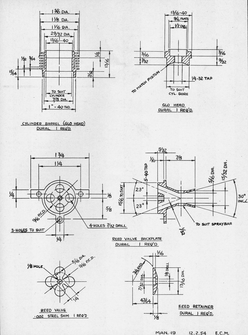
With this type of valve it is vital to smooth running at slow speeds, and ease of starting, to have an absolutely smooth flat surface on the valve face, so that minimum pressure is required to make the reed seal against the face. A piece of plate glass and metal polish will make an excellent lap for obtaining this surface. Perhaps the most difficult part of the whole engine to make is the reed itself. The number of petals has been restricted to four, despite the fact that there is room for more, because it would be exceedingly difficult to cut a more complex shape with a pair of scissors. That is how it is done: with a very sharp pair of stiff scissors which will produce the least amount of burr. Great care must be taken when cutting to see that the metal is not permanently bent in the slightest degree as the slight stretch produced in the metal will positively prevent a pressure-tight seal. It will be found that scissors produce a burr in one direction only, and if the scissors are not turned over during the cutting operation, the burr will remain only on one side of the component.
The other side will be the seating face and this may also be lapped lightly to remove any faint irregularities. However, not very much can be done by lapping anything so flimsy and, if the flaws are bad enough to be visible, it is advisable to cut out another part.
The reed retainer plate is contoured in such a manner that it has a flat surface 1/4 inch in diameter, which actually clamps the reed in position. From this flat outward a radius develops which should conform to the natural flexure of the reed when it is in operation. If a paper template is made to the dimensions given, it will serve as a useful guide during machining. The important thing is that there should be no actual corner on its surface which would tend to make the reed bend more acutely than elsewhere. The radius must therefore blend smoothly into the flat. .
When assembling the unit, take care to align the reed accurately with the ports and make sure that it does not move when tightening the center screw. Since any rubbing of the conrod on the retaining plate tends to unscrew this center screw, it is advisable to fit a locknut on its end inside the intake tube.
Finally, on the subject of intake diameters, larger bores may be used with success in conjunction with reed valves than with other types, and the 5/16 inch bore specified will be found to give sufficient suction for general use. A reduction to disappear with running, if it is not obvious and, when fitting, a half-dozen .005 7/32 inch diameter will give a very high fuel lift and make the needle control more sensitive, but will detract from performance. A good plan is to start small and increase the size as required; however, the drawing size will keep most people happy. A short intake, incidentally, is an advantage with this type of valve, and a long one does not improve fuel flow as with normal valves having fixed timing.
To those hardy souls who attempt this project, let us thank you for your interest and hope that you get as much satisfaction out of making and using the engine as your patience deserves. We would be grateful for a couple of lines on your findings and also as to whether you like this kind of article in MAN. How about a gas turbine next?
