Building the Little Dragon Page 4
The numbers on the photos correspond to the text.
Click on a photo to view it larger size.
Click on a photo to view it larger size.
Conrod
 Conrod 1.
 |
 Conrod 2.
 |
 Conrod 3.
 |
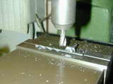
- The first and most important operation on the conrod is do drill and ream two 1/8" holes, the correct distance apart, and as perfectly parallel to each other as possible. After that, it's all file work. A good rule of thumb for reaming with Imperial reamers is to select a drill 1/64" smaller than the reamer to be used. The 2024 T3 bar was clamped under the mill/drill ensuring that the holes will be parallel. The mill X-axis can then be used to achieve the required between-centers distance.
- Stage 2 is to roughly saw the blank to size (it's easier to hold a large blank than a small one for the drilling and reaming operation). As the rod shank is also 1/8" wide, the holes and a steel rule can be used to mark out the sides. To profile the ends, make a set of 5/32" diameter filling buttons from drill rod. These are just two sliced, drilled through 1/8", and fully hardened. A short pin aligns the buttons either side of the rod. Then some work woth needle files and a vice produces neatly finished ends.
- Finally, the rod is polished to ensure all file marks are removed (not quite done yet here--as this photo shows). The reason for polishing is to remove points from which stress cracks may propagate. A small rod for a glow motor like this is not heavily stressed, but it's still a good idea. Also remember to lightly de-burr the rod holes, making one slightly deeper than the others. This one is for the intersection of the crankpin and crank-web which will present a small but significant radius.
Crankshaft
Well, I tried, but I simply could not force myself under pain of discorporation to make a shaft like that shown in the MAN drawings: 3/16", reducing to sharply to 0.164" for an 8-32 thread. Especially, I could not countenance a threaded steel washer screwed onto the fully threaded section as a prop driver. My minor revision--which involves a little more work, but does not change the operational characteristics of Roy Clough's design--is to extend the 3/16" section by 1/4" for a 7° taper onto which will press a "conventional" prop driver. The shaft will be drilled for a 4-40 stud.
 Crankshaft 1.
 |
 Crankshaft 2.
 |
 Crankshaft 3.
 |
 Crankshaft 4.
 |
 Crankshaft 5.
 |
 Crankshaft 6.
 |
 Crankshaft 7.
 |
 Crankshaft 8.
 |
 Crankshaft 9.
 |
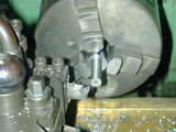
- A length of 5/8" 12L14 sufficient for the job, plus 1/32" for finishing is sawn off and chucked so that the full journal protrudes. it is then reduced " dit is a tight fit in its bearing. It does not matter if it will only just enter the bearing partially, as we must polish it anyway.
- A half-center in the tailstock (not shown here) is brought up for the final passes. 12L14 will turn to what looks like a smooth finish, but don't be tempted to think it's smooth. The thread-like machining pattern will result in high friction, so it must now be polished to a running-fit.
- We polish the shaft to the required fit in the front bearing using a piece of 600 grit glasspaper, backed by a steel rule, with lots of oil. Run the abrasive back and fourth, gradually using up new sections of the paper as it wears. If a trial fit shows more work is required near the web (as mine often sem to), just concentrate there a bit more until the bearing will spin freely on the shaft. If the bearing can be rocked, you've over done it--start again.
- Push the bushing onto the shaft and lightly scribe a mark at the end of the bush. Now taper the shaft for the prop driver. I have a number os shop-made D-bit tapered reamers and selected one with a 14° taper for this job. Finally, the shaft is drilled #43 and tapped 4-40 for the threaded stud. This is easier, stronger, and more crash-worthy than making the shaft in one piece.
- Photo #5 shows the crankpin jig being setup in the 4 jaw chuck, offset by the throw from the lathe axis. This means that the wobble measured by a DTP resting against the end of the aluminium jig will be equal to the stroke. The jig is drilled undersize, the drilled 3/16". There is no need to ream this hole.
- The hole is lightly countersunk to allow the web to rest firmly against the face, then removed and cut on a diameter projected through the center of the hole with the cut entering from the far side--ie, the sectio where the hole is closest to OD of the jig will remain un-cut. This provides adequate clamping force for small shafts, provided only light cuts are made while the pin is being turned.
- The pin is formed by progressively taking 0.015" wide cuts from the OD down to a point where the "interrupted" cut noise just disappears. Continue until the crankwek is withing 0.01" of finished, then make longitudinal finishing cuts untile the pin is a firm sliding fit in the conrod (which is why we made the rod before the shaft). Finish to a free running fit in the same way you finished the crankshaft.
- The crankshaft counter-balance cuts are made by using a drill of the right size to space the pin above the mill vice jaws with the shaft resting against the jaws on the side away from the camera. The "right size" in this case is a #29 drill (derived by some CAD construction lines and measuring--although a paper cut-out will give close enough results as well).
- Photo #9 shows the shaft and jig. It's a good idea to but a set of 3/32" letter and number punches. You may never build another Little Dragon, but if you do, you need to know which one of the dizens of crankpin turning jigs in the box is the one you want!
Prop Driver
In the MAN article of October 1950, Roy Clough really waxed lyrical over his "threaded hardware-store washer" prop driver idea. He even wondered why manufacturers did not adopt it. I think he's crackers. Alart from having no "grip", the concept depends on being able to run a thread on the front of the shaft all the way up to the shoulder. No die in my shop would do that without modification on the surface grinder that I don't have. 'Nuff said...
 Prop Driver 1.
 |
 Prop Driver 2.
 |
 Prop Driver 3.
 |
 Prop Driver 4.
 |
- A slice of aluminium is chucked and reduced to provide a stug 3/16" in diameter, 1/8" long that will accurately locate and center the props I intend to use (as the 4-40 stud would rattle around in the prop shaft hole of all commercial props in the 6 to 7" diameter range). Note that the blank is not drilled at this stage.
- A fine, straight knurl is then plunged into the face. See the Prop Drivers - How To page for full 'n boring details of this process.
- The driver is now reversed and held in a pot-chuck to form a pleasing profile that will blend into the front bearing. Matching the slope of the rear of the driver to the slope at the end of the front bushing (20°) helps greatly. The driver can now be drilled and taper reamed with the shop-made D-bit reamer (see my article in Issue #3 of Model Engine Builder for details on making straight and tapered D-bits). Final cuts are made rptating the chuck by hand, with lots of cutting pol until a hand press fir of shaft and bushing gives about twice the gap desired. Experience shows that this gap will halve when the driver is cinched up tight.
- The finished job. Nice. Time for coffee and Craftsmanship Appreciation. And I assure you that the finish this camera close-up claims to depict looks a lot better when viewed with the naked eye!