Feeney Construction Log Page 8:
Piston Rings.

 This is my first attempt at making piston rings, so please, please don't consider any of these words definitive. I simply studied the literature, thought about the problem, chose an approach, misunderstood it, and cheerfully plunged ahead. Surprisingly, it appears to have worked, and I'll know what to do next time. Stated simply, the objective is to produce a piston ring that, when compressed, will be perfectly circular and exert a uniform, radial force of an acceptable value against the cylinder wall for its entire periphery.
There have been quite a few ways of making piston rings described in various model engineering publications over the years. In my opinion, the best treatments given to the subject have been George Trimble, writing in Strictly Internal Combustion (SIC) [1], and the series by "Tubal Cain" the Model Engineer (ME) [2]. The Trimble method also appeared in the ME in a slightly less rigorous, but more clearly stated presentation [4]. The approach described by both of these authors are similar and involves an annealing stage where a circular ring is sprung open to a calculated gap, then heated to make this state the normal condition for the ring. If done correctly, when compressed by insertion in the cylinder, the ring will return to a perfectly circular planform and exert equal force on the cylinder wall around its entire periphery. In fact, the annealing fixture appearing in the Tubal Cain is a (credited) reprint of the Trimble fixture drawing as it appeared in the ME ten years earlier.
A very different way of making compression rings is described by Paul Chernikeeff in SIC [6]. His approach does not involve heat treatment of the ring. Instead, a gapped, oversize blank is clamped in ways that allow the outside diameter (OD) and inside diameter (ID) be turned to the finished sizes while the blank is in the compressed state. When removed from the fixture, the ring will relax to its open (and non-circular) "normalized" state, but produce the same desirable characteristics described above when inserted into a cylinder. The advantage of this method lies in the fact that no heating to a critical temperature is involved. So no heat measurement, nor elaborate precautions against the formation of "scale" are required. The downside (one of them) is that each ring must be turned separately, significantly increasing the effort required.
I decided that the Trimble method was the best choice, although I omitted the step that used an expandable mandrel to allow the ID edges to be chamfered which assists gas flow to the volume behind the ring, pressing it onto the cylinder wall, and compensates for the inevitable radius of the corners of the piston ring groove. The Trimble method covers both ring design and construction. I don't intend to replicate it here; that would not be ethical. Go buy the three back issues of SIC from RAW. This goes into considerably more depth than the version of the text that appeared in the ME. However, some of the highlights of the method are worth mentioning.
The theory of compression ring operation is presented in Part 1 (Tubal Cain's series actually gives better coverage of this aspect). Part 2 of the article presents a graph "envelope" representing the limits of ring properties, normalized for the cylinder bore (or compressed ring OD). The X and Y axes of the graph represent respectively, the effective uncompressed gap required and radial thickness. Any combination of values whose intersection lies within the "envelope" is acceptable. Dead center is not neccessarily the place to be. The text explains reasons why you may wish to consiously bias towards one of the four envelope boundaries.
It's interesting that the ring width (longitudinal thickness) plays no part in the "desirable" ring qualities—within reason that is. George wrote that he had studied a lot of commercial rings and concluded that a width to bore ratio of 1 : 0.0225 is a good ballpark figure, though thinner than a lot of earlier model engine designs have used. For the Feeney's 1.050" bore, this would make the rings 0.024" wide. Tremble does not say a lot about the ring groove, but an earlier series by Bob Paul in SIC [7] provides good rules of thumb for this aspect of design.
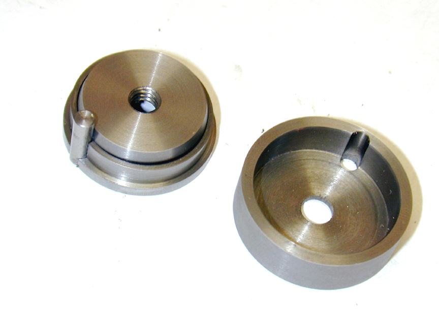
On the right is the cover that I got so very wrong. The clues were all there; I just chose to believe I'd discovered a mistake in the articles describing the fixture (all three of them, I ask you...) and proceeded on what sounded logical to me. Trimble's example (repeated by Cain/Walshaw), uses a ring thickness of 0.045 in a 1.000" bore ". The calculated spiggot diameter for the fixture is 0.941". The recess stated for the cover is in 0.950" diameter—only 0.009" larger. Obviously this cover is not going to slip over the expanded rings. But I wanted it to, so I called it an error, and made mine large enough to do so.
The penny finally dropped as I was adding the references for this page. Fortunately for my diet, the issue containing the Chernikeeff reference [5] included a drawing for the ring annealing fixture to be used by the "Jemma" 5 cylinder radial that obviously followed the Trimble method. The cylinders have a 0.750" bore. The ring thickness is 0.033". The mandrel of the fixture is shown as 0.715" diameter. The ID of the fixture cover is shown as 0.724"—b>again, a 0.009" difference, just like that of the Trimble drawing! I finally realized that I'd misunderstood how the cover is intended to work. It does not cover the rings, instead it is intended to clamp the rings, leaving what will be the working surface of the ring completely exposed during heat treatment.
All the clues were there. The Part 2 instructions say "As you tighten the bolt, press inward lightly on the rings opposite the gap to make certain they touch the mandrel there". No way can this happen if the cap covers the rings because (1) the cap bore will have to be wide enough to clear the expanded rings which are wider at 90 degrees to the gap than when measured across the gap diameter, and (2), you can't get your finger, or anything else into a position to press inwards! The next clue is the description of the heat treatment process (the name of the series in the ME, if it comes to that). The fixture is taken to 600 degrees F (315 degrees C) and coated in a borax compound, forming a heat resistant goo that will remain present as the fixture and rings are then heated to 1475 degrees F (800 degrees C). This prevents air exposure and scaling. I'd thought this step was just sealing the joint and felt it was overkill that could safely be omitted—especially since I could not obtain the compound required.
In the photo above, the crucible has been heated to cherry red, and is being allowed to air-cool. The article says heat to 1,475 degrees F (about 800 degrees C, or near-cherry red in a dark room) and that no soaking at this temperature is neccessary. Tubal Cain suggests a much lower temperature: 930 to 1,110 degrees F (500 to 600 degrees C), soaking for between 15 minutes and hour, provided you have a temperature controlled muffle furnace. He says if you have to use a gas tourch, anneal at 800 degrees C, holding for a "few minutes" only, and warns that the fine pearlite structure of the material is then lost due to changes that occur when the metal passes through the lower critical temperature at about 720 degrees C [3]. Walshaw asserts he has "...taken metallurgical advice on the matter [and] there is no doubt at all that the low temperature process is better". Another advantage is that no scale can form at these temperatures, so precautions are unnecessary. What to do? Both articles agree that the acid test for fully annealed rings is that they slip easily off the dowel with no desire to close up. If they close up, they are not annealed and you do it all again.
The ring gap is filed with a fine Swiss pattern needle file while held in soft vise jaws with a minimum of the ring protruding. There is no need to be precise in relation to squareness, it's not that critical, but it's not hard to get it right either. To check the gap, the ring is inserted into the piston insertion tool as seen here. This is just an off-cut bored to the cylinder bore, then tapered 15 degrees on one end. The taper gently compresses the ring to the bore size, allowing it (and the piston) to be passed into the cylinder with no fuss. It also lets you fiddle about with a 0.004" feeler gauge measuring the gap with no danger of scratching the cylinder bore. Bruce Satra described a simple jig to hold rings for gap filing in SIC [6]. This jig is sized to the ring in question, so would not be worth the effort for a couple of rings as used here. But if one was making a lot of rings of the same size, it would be well worth the effort. I may make one for the M5 rings.
 So, having determined all the ring characteristics, a lump of fine grained cast-iron is chucked and the a blind tube turned and bored. The ID is the cylinder bore minus twice the calculated ring thickness. The OD is the bore, plus an allowance for honing and polishing. Following recommendations by absolutely everybody, the turned length is sufficient for the number of rings required, plus at least two spares. Once the OD has been honed and polished to a close fit in the liner, we are ready to part off the rings.
 In this shot, I've brought up a piece of rod mounted in the tailstock to catch the rings as they are parted off. The thin parting tool is first used to true the end of the stack, then advanced by 0.025" plus the tool width to part off the rings. The extra thou is an allowance for polishing after the rings have been annealed. Note the very thin rings of cast-iron that have popped off just before the parting tool broke thru. This happened every time and must have left a bur. You can see why George Trimble advocated chamfering the ID edges of the rings on the ID.
 The next step is to snap the rings. I've made the George Trimble ring cleaver, seen in use here. The two blades were stacked in the Quorn for grinding and marked so that when dropped into the channel, the blades meet precisely at the points. The slit that positions the ring is precisely at 90 degrees to the blade channel in both axis, hence theory says that a ring cleaved using this tool will have a perfectly radial break. I've heard more than one experienced model engineer say that they still prefer to snap rings between their thumb nails, even though they've built the Trimble cleaver! All I can say is it worked fine for me. The two rings at the left rear in this photo have been cleaved, but I'm damned if I can spot where...
 Here is the crucible that will be used to hold the rings gapped for annealing. Basically, the ring will be held open a precise amount using a steel dowel pin whose diameter and position assures that the force will be applied at the center (radially) of the ring gap. This condition will obtain when the point on the ring ID diametrically opposite the dowel is in contact with the spiggot of the fixture on the left of the photo. So spiggot diameter, dowel diameter, and position radially are vitally important. The article gives simple formulae to derive all three. As can plainly be seen, the rings in this condition, stacked on the fixture are no longer remotely circular. Not so obvious is a 15 degree taper on the top of the spiggot that assists the opening of the ring as it is pushed into place.
Caution!
While writing up this part of the the series, I finally understood how the Trimble annealing fixture was supposed to be assembled. My misunderstanding resulted in a crucible that prooved very effective in excluding the air and preventing scaling without the use of a borax coating agent as described in [1]. What it did not do was clamp the ring stack and assure the absolutely correct gap spreading geometry was maintained during annealing. Read on...
 So pressing on regardless, the areas above the rings, and between the sprung-out rings and the fixture mandrel are packed with plain brown paper and the cover held in place with a cap head screw. The brown paper is intended to eat up any oxygen trapped inside the ring crucible to help prevent scaling. The article warns to only tighten the bolt finger tight as it always tightens up with heating. Strangely, mine did not. Perhaps because I made my fixtures from steel bar, not cast-iron as George Trimble advocated (I'm not that rich), or maybe because the clamped rings will "grow" a little during heat treatment and effectively tighten the bolt thread (when the cover is correctly used as a clamp instead of a cover).
 So figuring that the annealing process could not go wrong in any way that could not be re-done, I heated to cherry, and air-cooled. Here we see apparently positive results: my rings retained their gap. The rings were very faintly blue on the outside but had no sign of scale, while the steel fixture was the best blue-black all over that I've ever achieved. The brown paper had crisped, but not flashed and burnt, so I think the air-exclusion aspect worked pritty well. A clamp AND a cover would seem a good idea.
 The next step is to polish the ring faces top and botton, reducing them in thickness to the correct clearence in the ring groove. To do this, I made a fixture described in the "Tubal Cain" series [2] that allowes the ring to be compressed into a shallow counterbore. I made this larger than the cylinder bore seeing no reason to stress the ring with full closure. The ring is then lightly rubbed on 600 glass paper using figure-of-eight motion. I tried to work equally on both sides, using no more weight than the fixture to prevent accidental asymetric thinning of the ring. With only a thou to come off, not much work was required.
 What the devil are we looking at here? If I recall correctly, the ring on top has been polished as described above and the gap filed. The two below are still awaiting this process. I think this is right. Certainly the faces of the ring gap of the top most ring look more "finished" to me as I stare at this two month old picture writing these words. Hope that's right.
 The last task in manufacture is to gap the rings. All references seem to agree that 0.004" per inch of diameter is a good rule of thumb. They also agree that it's better to err on the large side. The reason being that the ring is going to expand and close up this gap when running due to friction and conduction of heat from the piston. If the gap closes completely while the ring is still expanding, the ring may break and very bad things will probably follow in consequence. Makes perfect sense to me.
 This photo just shows all the fixtures and a pair of finished rings. The real test is to assemble rings to piston and motor the engine a bit. Examination of the wear pattern will show if the ring seems to be contacting the cylinder bore uniformly. The Trimble article describes a way of knuckeling the ring onto the piston so as to prevent it taking a permanent "set". Both references note that annealed cast-iron will exhibit a degree of hysterisis: the gap will be wider after fitting to the piston, but will return to the "relaxed" gap after insertion and removeal from the bore (or insertion tool). Amazingly, that's exactly what I observed (using a virgin ring to perform the comparisons). As it finally turned out, I've not needed the two extra rings I made, but I'm glad I've got them
Here's the compression ring and wrist-pin retaining ring/circlip in place, showing how much float there is in the groove for the ring. The figures used for ring groove size were drawn from Bob Paul's SIC article [7] and I'm sure I got them right, though looking at the photo now, there seems to be a tremendous amount of movement possible.
This photo just shows all the fixtures and a pair of finished rings. The real test is to assemble rings to piston and motor the engine a bit. Examination of the wear pattern will show if the ring seems to be contacting the cylinder bore uniformly. The Trimble article describes a way of knuckeling the ring onto the piston so as to prevent it taking a permanent "set". Both references note that annealed cast-iron will exhibit a degree of hysterisis: the gap will be wider after fitting to the piston, but will return to the "relaxed" gap after insertion and removeal from the bore (or insertion tool). Amazingly, that's exactly what I observed (using a virgin ring to perform the comparisons). As it finally turned out, I've not needed the two extra rings I made, but I'm glad I've got them
Here's the compression ring and wrist-pin retaining ring/circlip in place, showing how much float there is in the groove for the ring. The figures used for ring groove size were drawn from Bob Paul's SIC article [7] and I'm sure I got them right, though looking at the photo now, there seems to be a tremendous amount of movement possible.
References:
![]()
Back to Feeney Journal front page