Editorial
First up, sorry this edition has appeared "late"—I do try hard to have each edition appear on the first of the month, each month. And the December issue was ready on schedule, but unfortunately, the mechanism that pushes the files I write out to the world via DSTC's Archive Site had silently and sadly gone belly-up while the only sysadmin who knew the name of the process and had the passwords required to restart it was on vacation! Needless to say, we won't be letting that happen again...
December again already (Bah, Humbug). Another year almost gone with all those projects that where almost close to finished still almost close to finished. On the positive side, hits in the past month have been nothing short of astonishing. We started November with the counter at 83586. The official figure as I replace last month's front page with this one is 92277. That makes the number of hits for November 8,721 sustaining the upward trend seen of late and means we'll break into six figures during December. Very gratifying... thanks!
Engine building has taken a back seat this month to a spot of collecting, and some model engineering in the tools department. The first year after buying my lathe was spent doing virtually nothing but making tools—frequently in order to make more tools. Many of those, like the George Thomas retracting tool holder, see constant service in the workshop. Others like the Quron Cutter Grinder and taper turning attachment see less frequent service, but when they are called upon, I'm always glad I spent the time to make them. This month, I've invested some more time making accessories for the Quorn, prompted by the miserable state of the larger drills in my drill stand.
It's also been a busy month answering emails from readers. Sometimes the answer lies already burried on this site, someplace; sometimes not. One of the "nots" was in relation to the little external hone mentioned in last month's Tech Tip (which so many seem to have found of value). The question, and one that I should have anticipated, is "where can I get it?". The answer is Bruce Engineering and I've added the contact details I have to the Suppliers Page. I've no idea of the current price, so send them a (snail) letter for details. If you discover they are "on-line", please let me know so I can update the details.
And lastly, those on tenderhooks from last month will be wondering where the answers are to the Rear Rotor Madness pictures so they can see how many they identified correctly. Well, due to the large amount of stuff to present this month, it will have to be postponed until next. That's my ready excuse anyway. Sorry, really...
Midlands Mia Culpa
For last month's edition, Ken Croft sent in some great photos of engines that he'd taken (the photos, not the engines  ) at the 2003 Midlands Model Engineering Exhibition, including some more of Barry Hares' almost complete Rolls Royce Eagle 22 (more on that later). In the process of posting them, I "found" the pics that Ken had taken of the 2002 show had never quite made it to final publication either (big whoops). So I duly added them under the Shows and Exhibitions tag, then completely forgot to mention the fact to all you repeat visitors who depend on this page to tell what's been added to the twisty little maze of pages. Sorry 'bout that 99...
Rolls Royce Eagle 22
 I've mentioned master modeler, Mr Barrington Hares, before on these pages as the builder of the outstanding 1/5th scale Rolls Royce Merlin that won the Gold Medal and Cup at the 1982 Model Engineering Exhibition in England. As prizes for model engineering go, this one is unquestionably The Big One. Ken has been snapping pics of Barry's latest project for the past few years at the Midlands show, and in the past month, Barry was kind enough to send me some shots of his own and add some words regarding this exceptional model. I'm frequently accused of being a bit free and easy with the adjectives, but this time, I'm not even going to try. Just go now and look in detail at his accomplishment.
Six Facet Drill Sharpening
 As mentioned in the Editorial, the sorry state of my larger drills has been weighing heavy on my mind for a while, and while the Quorn provided a way of sharpening them if need really be, the required setup was not what I considered optimal. Remembering an article from Model Engineer cicra 1994, I dug around, located it, and decided it was a worthy project. In the process, I plan to revise and update all the Quorn related material, so as usual, a simple project gets turned into a complex one. The new accessories, although not fully complete, are encouraging and at least part of my larger twist drill stock has been restored to better than new cutting ability ("restored" to better than new? Something wrong there...) The usual method of sharpening twist drills employs what is termed "conical back-off". There are other ways, amongst them 4 and 6 facet sharpening. The photo here shows a drill sharpened using (count them) the 6 facet method. What I've read says that this method, correctly applied, will result in a drill that drills straighter, closer to "true" size, with less force required for the same feed rate in comparison the one with conical back-off. The page detailing the tooling made for the Quorn and the sharpening process it self is under construction on the new Quorn Tool and Cutter Grinder page (And yes, the intersection of lip and margin closest to the camera is chipped. Didn't even notice until I examined the photo! This drill will have to be done all over again).
Engine of the Month: Limited Edition Owen 2.8SP Diesel
Since Gordon Burford of Taipan fame retired, the number and range of Australian produced engines has been limited to small production runs by a handful of individuals. Specifically, Gordon Burford (you can't keep a good man down), Ivor F (in consultation with Gordon Burford), David Owen (sometimes in conjunction with Gordon Burford), Phil Morten, David Burke, and probably several others I don't know about (I'm not going to include my own AHC's here as the quantity so far, thirteen to be precise, is too low to qualify). While none of these worthy gentlemen produces great quantity, they do produce great quality. So when another batch becomes available, they are always snapped up fast by collectors and flyers alike.
 Now I happen to be privy to the fact that David Owen is about to announce a limited edition his "new old" 2.8cc side-port diesel design (pictured here). This engine was designed by David in 1990, and has been produced intermittently in small numbers. The porting system is a full 3-port Schnuerle type. Induction is through a large transverse inlet port located under the exhaust port which itself is angled rearwards at 45°. This inlet porting layout is unique and results in efficiency rivaling more common shaft and disc rotary valve types. The benefits are lower weight and a compact engine with the needle or carby controls at the rear for safety.
The crankcase is a heat-treated investment-casting, with the crankshaft running in two special German ball races. The crankpin is a very hard INA needle roller pressed in to a ground steel shaft. The wrist pin is also an INA needle and the conrod is long-wearing 7075-T6 alloy. All engines come with a special, compact and lightweight silencer that is designed to reduce the noise levels dramatically and at the same time, collect most of the exhaust oil. It is simply attached to the angled exhaust duct with the silicon tubing supplied and is removed after each flight, allowing the oil to drain into a paper towel for proper disposal.
Specs are:
| Bore | 15.0mm | 0.590" |
| Stroke | 16.0mm | 0.630" |
| Capacity | 2.8cc | 0.17 cuin |
| Weight | 190-205gm | 6.75-7.25 oz |
There will only be about 50 engines produced, all by hand on David's Hardinge and Overbeck precision machine tools. David hopes to have 20 of this batch available before Xmas 2003, with the remainder to ship within 6 to 8 weeks. Three models are available:
- OWEN 2.8SP R/C, fitted with an excellent Thunder Tiger carb
- OWEN 2.8SP STANDARD, fitted with a standard venturi for C/L and F/F
- OWEN 2.8SP TEXACO, fitted with a small-bore peripheral venturi assembly, giving very low consumption on larger props for A Class Texaco events
If you'd like to reserve one of these, email David for details at
owendc@tpg.com.au, or write to him at OWEN ENGINES Australia, PO Box 1739, Wollongong, NSW 2500, Australia.
Skew Gears for Four Strokes (or, that blasted Feeney, Yet Again)
Now a bold experiment: It's said that for any printed work, the audience will drop by half for each equation that work contains. If this holds true, I can expect the hit counter for January to be about one quarter of that reached in December because I'm about to lay a couple on you. First a different sort of warning: I'm no kind of trained "professional" machinist. All the material following (in fact, all the material on this web site) is just my research, observation, and deduction. I could be, and frequently am, completely wrong! Follow any advice and recommendations here at your own risk...

Now I don't know about you, but I've often wondered why some commercial model 4 stroke designers, Saito for example, choose to drive the cam shaft with simple 2:1 spur gears, while others—like the eviscerated OS pictured here—choose a more complex skew gear arrangement. ET Westbury and Prof. Dennis Chaddock also appear to have favored helical gearing for this purpose (ref [MTO2] notes that the terms "spiral", "helical", and "skew" are synonymous when talking about this type of gearing).
 For the amateur constructor, cutting spur gears is a very simple, if relatively exacting operation (this photo shows a trial gear I made some years back and the shop-made hob that cut it). Cutting spiral gears however, as this past month's research has disclosed, is far from simple. I've discovered that there are at least four ways to accomplish this operation, each requiring some rather specialized equipment and complicated set-up. Even for commercial manufacturers, this is going to increase the cost significantly over their spur gear competitors, so why do it? Admittedly, the use of skew gears will place the cam shaft at right angles to the crankshaft which, in turn, can lead to a better placement of pushrods and rocker arms, but there's got to be more to it than that.
The answer it turns out, lies not in the soil , but in the math. First, some gear-related definitions:
Involute
A curve that is most commonly used today as the optimal shape for the face of gear teeth for industrial purposes. The cycloidal form is still encountered in some applications, but mostly, gears and cutters are involute. See any text on gears to find out how to generate, or approximate the involute curve. The description in ref [WSP17] is particularly suited to amateur machinists.
Diametral Pitch
Term applicable to imperial measurement, abbreviated to DP, is a ratio of the number of teeth to the pitch diameter. A designer can pack any number of teeth onto a given circumference—just vary the tooth size. But for two gears to mesh correctly, they must have the same DP. Involute gear cutters are made to (mostly) whole number DP values, although for any given DP, 8 different involute cutters are needed to cover the number of the teeth from maximum to minimum—the maximum being infinite, ie, no curvature, or a "rack" of teeth. What dictates the minimum is left as an exercise for the.... No! Stop that!
Pressure Angle
The angle between a tooth profile and a radial line at the pitch point. Today, industry has largely standardized on 20 and 14.5 degrees with 20 being the preferred value as it results in a stronger tooth (the odd 14.5 figure was chosen I believe to simplify calculations in the days before hand held electronic calculators).
Pitch Point
The point of tangency of two pitch circles. That is, the point at which the gears "mesh".
Pitch Circle
A circle, centered on the gear axis, that passes through the pitch point.
Pitch Diameter
Abbreviation PD, is the diameter of the gear at the pitch circle. Hence the distance center to center required to mesh two gears is one half the sum of pitch diameters.
The last 4 definitions are simplified for our purposes here, and like the Object Oriented programming terms class and instance, it's impossible to define one without mentioning the other and vice versa, only more so because there's four of them!
Now, all the foregoing was required to simply to explain that if we are going to cut teeth, we need a cutter and that cutter will be specified as having a specific Pressure Angle and Diametral Pitch (or Modulus, if we were using metric nomenclature). We started this whole business because we wanted our cam shaft to revolve at one half the engine crankshaft speed, and so required a 2:1 gearing ratio—which is to say one gear must have twice as many teeth as the other, and because they must mesh, they both must have the same DP.
The spur gear designer looks at how strong the gears need to be having regard to the speed and materials and how much space is available to pack the gears into, calculating the gear sizes from the formula:
PD = N / DP
where "N" is the number of teeth. Notice that no matter how you cut it, for the same DP, the diameter of the gear is going to be directly proportional to the number of teeth. So you end up with a little gear on the crankshaft driving a gear of twice that diameter on the cam shaft.
The helical gear designer still has to arrive at 2:1 gearing, so still requires twice as many teeth on the driven gear as on the driver, but now the formula must take the angle of the spiral into account:
PD = N / (DP * Cos A)
where again, "N" is the number of teeth, but this time, the PD (and hence the overall diameter of the gear, which will be a little larger) is increased by dividing by some value less than one, this being the cosine of the angle "A", which is the angle of the helix relative to the gear axis. If we want the cam shaft to be at right angles to the crankshaft axis (and we do), the two helix angles must sum to 90 degrees. The easy way out is to choose 45 degrees as the helix for both gears and end up with a big one and a little one—with pitch circle diameters also in the ratio 2:1, just like their skew counterparts, only slightly larger (the Sin and Cos of 45 degrees both being, as we all remember, "one on root two", or 0.707 thereabouts—an easy number for air-minded folk to memorize).
But wait! Because there is that fourth variable, we can solve the equations for a set of 2:1 gears using the same PD, but with different helix angles:
PD = N / (DP * Cos A) = 2N / (DP * Cos A')
or
Cos A' = 2 Cos A
where
A + A' = 90
Now with a little jiggling, we can derive the magic angle and this comes out at about 26 degrees 34 minutes for the 20 tooth driven gear, and 63 degrees 26 minutes for the 10 tooth drive gear. Given these spiral angles, the PD's will remain the same for any number of teeth and DP that produce the required 2:1 gearing.
A pragmatic designer is probably going to round those to the nearest ten degrees in order to simplify manufacture and live with the fact that one gear will be about 13% larger than the other—that's still a lot better than 100% which is where we'd be if we'd gone with spur gears. This fact is probably drummed into mechanical designers during their formative years, so as to be second nature. To me it was shock, surprise, revelation!.

That's possibly why OS, Feeney and Westbury chose skew gearing and the odd angles. Even though the skew gears are going to be bigger than their spur counterparts with the same number of teeth, the relative sizes of the gears can be managed using the skew angle, allowing the driver gear to be made larger and hence stronger. To achieve the same tooth size, a spur gear driver would need twice as many teeth, meaning the driven gear would need twice as many teeth, and the diameters (on the PC) overall would double. By using skew gearing, we achieve a more compact design for a given strength. The photo here shows a pair of Feeney gears and the helical hob used to produce them. The tooth profile is "distorted" on the face by the helix angle, but it's plain to see that the gears are of roughly similar diameters, yet one has twice the teeth of the other.
It appears that the 10 tooth "driver" gear has larger, stronger teeth, but this is an illusion brought about by the helix angle slice. The profile of the teeth taken at some point normal to the spiral would show the teeth on both gears to be the same (otherwise they would not mesh).

Saito frequently uses spur gears mounted at the front. This places the crankshaft and camshaft axies in line (you can see by the location of the tappets and push rods here that both cam lobes must be behind the large spur gear).
Hence the driver gear must be integral with the main crankshaft and be of equal or grater diameter to maintain strength of the shaft. This means that the driven gear must be twice that diameter (as measured on the PC), hence the "hump" on the shaft journal. If we wanted the crankshaft and camshaft axis to be in-line with skew gears, this could be simply done by using one left-hand and one right-hand gear, with equal helix angles. But because the angles must be the same, we can't play games with the angles like we did before to manipulate the PC diameters, so there is no advantage that I can see in using skew gears arranged like this. In fact, the extra friction generated by the end-thrust inherent in skew gears would be a distinct disadvantage.
For the Feeney and Westbury designs, with cam assemblies and valve gear at the rear (a safe place during an unexpected encounter with the ground), a similar argument may apply. Then again, maybe they just plain really, really wanted a transverse cam shaft and hang the expense!
Back to the Feeney Gear Problem

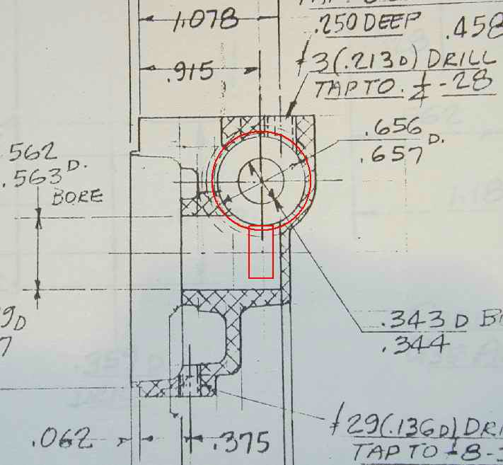
 Skew gears with a 45 degree helix angle are a stock item in the HPC (UK) catalog. They can supply in steel, brass, delrin, etc and the cost is very low, even in one-off quantity. The big question is can the Feeney casting accommodate the change in gear diameters? With 40 DP, 45 degree skew gears, the change in center to center distance is nominal (-0.008"), but the driven gear is larger (a 45 degree helix angle yields 0.757" OD compared to 0.577" for the 30 degree helix). The two pictures here show a photo of the relevant Feeney drawing sheet (I was too lazy to scan it), loaded into TurboCAD and scaled to 100%, with the outline of the two gear options superimposed. On the left, in blue, is the 30/60 gear pair as called out by the drawings. On the right, in the red corner, is the HPC 45/45 set. If these were used, the case would be very thin at the aft end (assuming the drawing accurately reflects the case as cast), and the amount of metal supporting the tappet guides would be reduced a little. There are other issues in making the change, but they are minor and I won't bother with them here—suffice to say, the substitution is not completely impractical.
Thrust face
 One last point about skew gears. Like threads, skew gears can be cut as left hand, or right hand (an easy way to tell which is which, and this applies to threads too, is hold it with the axis horizontal; if the slant of a crest points down towards the right, it is right-handed; down to the left means left-handed). The importance of this is that working skew gears generate axial thrust, the direction of which depends on the "handedness" of the gear, direction of rotation, and which is the driven gear (ref [MH25]). In Reference [ME45], John Hellewell, writing about the Westbury Kinglet gears, states that while spiral gears provide a smoother drive than spur gears due to the longer, gradual engagement of the teeth, they also suffer have one outstanding disadvantage: end-thrust.

To understand this, imagine one gear being held stationary as the other turns. The effect is like a bolt and nut. The rotating gear will move in a direction governed by the direction of rotation and thread "hand" exactly as if it were a screw thread. In operation, both gears will experience this effect, which will be imposed on the shafts to which the gears are fixed. So taking this illustration, if gear 'B' were fixed and the right-hand spiral gear 'A' rotated as shown by the arrow, it would have to move toward the top of the diagram. Even with everything free, this force remains on the driven gear. Changing the direction of rotation, or direction of the spiral will reverse the direction of the thrust, as will swapping which is the driver, and which is the driven gear (ref [MH25]). The greater the spiral angle, the greater the thrust load, so with our 30/60 arrangement, the 60 degree helix driver affixed to the well supported crankshaft takes the lion's share, while the driven 30 degree cam shaft, sitting in relatively light bearings, has a lesser end-thrust applied. This is good, but probably not massively significant.

The Feeney design calls for left-handed gears. This means that for normal crankshaft rotation, the force on the driver gear will be pulling the crankshaft rearwards. As this can't happen, the net effect, unless I'm completely wrong, will be that the gear will be trying to pull itself off the shaft it is pressed onto. And, given the way the case is bored to insert the cam assembly, the force from the driven gear will be trying to push the cover plate off the crankcase! This seems completely backwards to me. If right handed gears were used, the driver would be being forced against it's shoulder on the crankshaft, and there would be no load on the cam cover plate at all. Can Feeney have got it that wrong? Look at the illustration in the previous paragraph which depicts right hand spiral gears. Imagine the crankshaft attached to gear 'A', with the front of the engine at the top of the figure—in other words, the viewpoint is underneath the crankshaft, looking up. The direction of rotation shown for the driver gear 'A' is correct for normal rotation. Clearly, the driver gear is now being pushed against its seat on the end of the crankshaft, and the driven gear is being pushed into the crankcase cavity (as shown in the sections A-O-B-C and D-E of the GA here). To me, this looks "correct", even though the spiral direction is opposite the that called out by Feeney. Must check one of Westbury's skew designs (The Wyverne, Kinglet, or the Channel Island Special). More mystery; more investigation required; more next month...
References:
Thanks go to a reader/supporter in the USA who took the time and trouble to copy and mail me the two MW articles, to Eric Offen who dug into his copious ME archive for the Westbury related material, Bert Streigler for the OS skew gear shot, and all the Motor Boys for trying valiantly to make sense of my sudden skew gear obsession. Much appreciated!
[MH25]
|
Green, RE (ed): Machinery's Handbook, Twenty-Fifth Edition, Industrial Press Inc, New York 1996, pps 1984-1998.
|
[MTO2]
|
Burghardt, HD et al: Machine Tool Operation Part II, McGraw Hill, fourth edition 1960, chapter 10.
|
[ME45]
|
Hellewell, J: Spiral Gears for Petrol Engines, Model Engineer, June 21, 1945, p 581.
|
[MW1]
|
Cooper, J: Gear Cutting Adventures: Helical Gears, The Machinist's Workshop, June 1999, p23.
|
[MW2]
|
Sexton, T: Experimental Helical Milling Attachment, The Machinist's Workshop, June 1999 , p12.
|
[WSP17]
|
Law, I: Gears and Gear Cutting (Workshop Practice Series Number 17), Nexus Special Interests Ltd, 1995 , Chapters 2, 6.
|
New Books and Magazines This Month
 While one new book did enter the library this month, it's such a monster (and contains enough mathematical formulae to qualify as an academic text) that I'm going to hold off even disclosing the name, just yet. Instead, I'll delve back into the archive for one of the works I used researching drill sharpening as part of this month's shop activity. That is: Drills, Taps and Dies, by "Tubal Cain" ISBN 0-85242-866-9. This was the Model Engineer nom d'plume for the late Tom Walshaw (the biblical reference being to the son of Lamech and Zillah, "an instructor of every artificer in brass and iron". Genesis 4:22, "the forger of every cutting instrument of brass and iron"). This book is volume 12 in the Nexus (originally Argus) "Workshop Practice Series"—a series which now amounts to 33 volumes. Much of the material in this series is either a reprint, or expansion of material published over the years in ME, although there are some that contain totally new material. This is no bad thing as ME is a wonderful resource, but not everyone can afford the bookshelves to hold back issues of a magazine that has appeared continuously every two weeks (and at times in its history, weekly) for more than 100 years!
Back to the subject. The #12 volume presents the theory and history of things you rotate into or around metal to produce holes and threads. Two appendices contain tables of drill sizes and threads that we are most likely to encounter in common use in the USA and England (and even out here in the poor colonies too). This is refreshing because so many similar volumes take a parochial view of "not invented here, so not of any interest"—a lamentable trait on both sides of the pond. The author's style is very readable and his focus, very practical. I think this quote from the Author's Preface sums up his philosophy:
"I cannot be the only one to have been struck by the fact that in Industry the main preoccupation is with tap sharpening, whereas the jobbing worker, the model engineer, and amateur generally, is beset with the problems of tap breakage!"
A good read, and a good reference work on a topic we take far too much for granted. See the Suppliers Index page for places to buy a copy.
Barton Model Products now on-line
 If you ever subscribed to the magazine Model Engine World in its first incarnation, you will remember the name John Goodall as the editor/publisher. The business name that MEW subscriptions sold under was Barton Model Products or BMP for short. BMP also traded engines and the "classified" pages of MEW were by and large, advertising for BMP stock (with occasional external placements). Neat trick. I pay you to send me your advertising! Still, overall, I'd have to admit that I quite enjoyed MEW as a magazine and keep silent about the rest. When JG sold the magazine name and good will, he retained the BMP business and has continued to grow his engine trading enterprise. BMP had a rudimentary web site, but this disappeared with Goodall's editorship. This past month, I discovered that BMP has a new on-line presence at http://www.bamopro.co.uk/about/front.asp. I'm generally a bit wary of "asp" URL's, but this one seems benign enough. The site is well designed and the Terms and Conditions page gives payment methods as cheque, money order, direct transfer, or Pay Pal (no credit card facility as such). I think the prices tend towards the high side of reasonable, but I always think that when I'm the one shelling out . Still, if you really want it and he's got it, the choice is simple. The image used as the teaser for this paragraph has no direct connection to the web site, except by name; it's a BMP 3.5 cc diesel (of an engine in the Straniti collection). I spotted one in his listing for a mere 275 UK pounds, US$466, A$648...
More Gallery Pictures
 Some nice pictures of equally nice free-lance engines arrived during the past month. These have been added to The Gallery for your enjoyment. Ever since I can remember, I've always liked cut-away diagrams and exploded view pictures, so this shot of a McCoy 60 inspired twin ball race glow engine really appeals to me. Just before my Quorn was finally assembled, I shot a whole roll of 35mm film of the nearly 200 individual parts, artfully posed, multiple angles. Unfortunately, the film was not winding through the camera. Grrr... At least modern digital technology has made that a problem of the past.
Another Approach to the AHC Diesel
 As mentioned in passing last month, the Empire Motor Boy, Ken Croft, feeling left out with all the other AHC's being build, decided to make one himself (the picture here is a cunning composite—there's only one engine). All Ken's motors are honest, working class motors, not hanger queens (like a lot of mine), and having followed all the trials and tribulations we'd had collectively with this design, Ken decided his would sort it out for once and all, yet maintain the same outwards appearance of my drawings. Not that the AHC is a bad engine; it starts easily, is non-critical to adjust and runs well enough for it's size and limitations. But there's always room for improvement.
 As we'd all pritty much concluded that the stylish work around the exhaust ports and the poor thermal connection between liner and cooling fins was probably costing some power, Ken focused his attention in this area. The thermal tie is easily solved by a cooling muff that threads directly onto the cylinder liner. But the AHC design uses the jacket to press the liner into the case. This is another indirect problem, as part of the liner/case seal depends on how tight the jacket can be tightened up with no positive way to grip it. Ken's solution seen here is a threaded ring that secures the liner. The ring is drilled for a pin spanner to tighten it up. The cooling fins then screw direct to the liner, seating on the ring insert in such a way that the detail design change is undetectable.
 Ken reports that his AHC fired up right away and is just as easy to start and forgiving to handle as the ones built in the USA and here in OZ by yours truly. Definitive figures on the advantage bestowed by the better thermal connection will have to wait on Ken running his AHC with the same brand and size of prop that Bert and I have used in tests, but initial figures of 7800 RPM, with more to give after it is run-in are encouraging. Ken did say that the piston liner fit is about the best he's ever made, and while that will contribute to the good, early performance, it's almost certainly not the whole story. The engine is now destined for a Gilbert Shurman "Rambler" scaled down to 56" span. The plan Ken has does not show the airfoil section used, so if you can help with this minor detail, please let us know.
Tech Tip of the Month: Making Plastic Fuel Tanks
A well made engine will last forever (almost), 'though parts of it may not. Most notable is the propensity of plastics to return to the sludge from whence they came, over time. Old engines frequently had small plastic fuel tanks fitted that held just enough fuel for a run that could boot a free flighy model to heights from which it would never be seen again. This has become a feature of the past, with reliable R/C equipment, throttles, and fuel tanks the size of milk bottles (we once heard a "modern" R/C flyer telling all and sundry that if the engine stopped, you crashed. Kids! I dunno...) These plastic tanks were frequently heat formed over a simple male die from whatever piece of Perspex was available in quantity, leading to some colorful items. Today, this stuff is hard to find, and making die and formers to press out one tank is a bit of a pain, so Motor Boy Bert Streigler came up with the observation that the plastic handles of screwdrivers turn well and come in all the right colors. My restored ED Baby was in need of a tank (as are the Baby repros made from Roger Schroeder's kits). ED made tanks in green and yellow, so imagine my joy on spotting a grungy, disreputable, Phillips head driver lying all forlorn in the gutter just off campus. Joy! Here was Baby's new tank, for shure!

Phillips 'drivers can be chucked by their shaft. Depending on the length, flat blade drivers may need a hit on the grinder, especially if they are of the short, stumpy variety—which are cheaper if your gutter is not so well stocked and you have to resort to the seconds bin at the local hardware store. The plastic will get soft if it heats up, so the tool needs to be as sharp as you can hone it. For turning, plastics seem to like high speeds, but beware of the heat build up. Amazingly, some standard cutting lubricant definitely helps giving a shiny finish off the tool with no polishing necessary.
I turn down to the required OD first so the solid stock provides support. Next the ID can be rough drilled and finish bored to size and shape. The inner end is generally either hemispherical, or has radiused edges to emulate the male die used to form the original. After parting off over length, the tank is mounted on a mandrel turned to be a light press fit in the ID in order to finish off the rear and drill the mounting and vent holes. If you turn this mandrel from a piece of wooden dowel, you can drill into it when forming the holes which helps prevent the plastic from cracking as the drill breaks through (assuming you don't have a set of drills specially relieved for drilling plastic—who does?)

My bargin basement—sorry gutter—item shown here was not quite right. By the time I'd turned down enough to get past the hand grip flutes, the OD had reached the required ID! Still, I continued on and mounted it as seen here to show the concept. The end of the tank was radiused with a form tool. The radius used was what I had readily available and is too small—if this had been "for real", I'd have gone to the trouble of grinding up a correct one, but for demonstration purposes, it'll do. So next time you're dragged off by She Who Must Be Obeyed to the the local flea market on a Sunday morning when you'd rather be flying, look for the silver lining and hunt up old Stanley plastic handled screwdriver bargins—the larger the better!
New Engines in the Engine Finder
I'd really intended to add some new engines to the Engine Finder in the form of "mini-reviews" to go with pictures taken recently, but time, skew gear calculations, and drill sharpening have run away with me. But rather than completely leave them until next time, simple images have been added for the following:
- Alag X4
- Bantam Twin
- BMP
- DC Manxman
- DC Rapier (green)
- DC Wildcat
- Frog 250
- Kingcat
- Mills Bros 2.4 RRV
You can't fail to have noticed the these have not been hyperlinked above, so you'll have to actually look them up in alphabetical order. Who knows? You may spot another engine that you didn't know was in there...
 Midlands Mia Culpa
 Editorial