Vale: Bill Brown
With the start of 2003 comes sad news from the USA in the passing, at age 91, of Bill Brown—a man called, with some justification, the Father of the Gas Model Engine. William Likens Brown IV was born on May 11, 1911. He rose to national fame in the US modeling scene during 1933 when a model called Miss Philadelphia III, powered by an ignition engine that he had designed and built swept every major category at the National Model Airplane Championship meet. At this time, there were no categories for "gas" powered models because there were no commercial engine manufacturers. This enabled Bill's friend Maxwell Bassert (the builder and flier of Miss Phily) to enter in events traditionally flown with rubber power. If this seems unfair, you need to consider that gas models needed to be huge to carry the weight of coil, battery and engine. Add to this the facts that engines had to be hand-built and that there was no extant body of knowledge on how they operated, nor how a gas powered model should be designed and rigged, while rubber powered models were well understood and developed.
In 1934, Bill and his father (Bill Brown III) founded The Junior Motors Corporation of Philadelphia which they managed and ran until 1940. Their engine, called the Brown Junior, was an enlarged (.60 cu in) and refined version of Bill's original that led to the introduction of gas powered models as a national competition class and spawned an industry. Now you can argue that it could have been anybody; the time and technology were right; Ohlsson and others were doing the same thing in the USA and ET Westbury, CE Bowden and Frank Whittle (yes, THAT Frank Whittle) were doing similar things in the UK. But it was Bill and his father who thought through the problems and made it possible for modelers to buy not only a reliable engine at an affordable price, but also all of the required paraphernalia needed to make it a practical power plant for model aircraft.
Following the separation from Brown Junior Corp, Bill went on to design the first CO2 powered miniature reciprocating engines. A Master Machinist, he worked at Leeds and Northrup, the Franklin Institute in Philadelphia and the Ordinance Research Laboratory. In later years, he received National and International recognition for his very significant contributions to aeromodeling. It's a sad fact of life that we've all got to go sometime; Bill leaves us having given far more than most.
Magazines and Books of the Month
Not a lot this past month. Instead, I spent some time moving 15 years of Model Airplane News out of storage and onto my library shelves. This required reinforcing the spine of the cover of every issue, Feb 1950, through Dec 1964 (reattaching in many cases) and naturally, skimming each issue on the way through. This process led me back to the Little Dragon by Roy Clough Jr in the Oct and Nov issues for 1950. This is the engine that inspired the EZE Series developed by Tom Crompton. An unusual feature of the original design is the use of a section of seamless steel tube for the cylinder liner (Clough's instructions say that honing the tube ID is optional!). His design allowed the ports to be cut with a hacksaw (very easy). The downside is two-fold, as I see it. One: Ron's Dictum #7b states that slit things always close up and since the transfer port and passage is formed by creating a slit from the bottom of the tube upwards, I think the piston would be nipped at BDC which is not good. The second problem is that by using a section of tube as the liner, the crankcase needs a blind bore to locate the liner which complicates the machining a little. Still, it's a relatively practical design, and this leads us to the next topic:
3D CAD
While I'm comfortable with CAD, having produced now some 28 engine plan sets using TurboCAD, the 3D capabilities of the package have remained a mystery to me. IMSI, who make the package, supply a comprehensive set of tools with little to no documentation of a tutorial nature. Browsing the web recently led me to CadCourse who supply numerous tutorials based on TruboCAD. After examining the on-line sample, I took the plunge and forked out US$30 for their "Spacestation" package. This uses what I'd term "follow the bouncing ball" type animation with voice narration to show how to take 2D drawings (in this case, the International Space Station drawings downloadable from NASA) an convert them to a 3D model. Call me old fashioned, but I like fast pacing in a course of this kind. You can always replay a sequence if it's too fast, but if it's slow, or dumbed-down to a "Mumble For Idiots" level, it's likely to put me to sleep, and I'll probably abandon it. The course author, Robert Berry, has paced this one just right—for me at least. You watch him do some tasks, listening to the explanation, then try it for yourself.
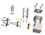
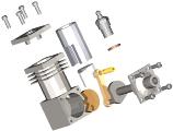 So, armed with this New Knowledge, I CAD'ed the MAN Little Dragon referred to above, then converted that to 3D with the results as seen here (I know, I should have been working on the Morton, or the Sparey Twin, or...). The ray-tracing was done by TurboCAD and I could not find a way to tell it to use more polygons when interpolating the facets, hence the rather chunky faceting of cylindrical objects like the cylinder and piston, etc. But it does show how the engine goes together well enough. It it worth the effort? Dunno. This took me about 6 hours, but I'm still learning. Also, I certainly had no trouble picturing the parts in my mind from the 2D drawings, but not everybody is so blessed, so I'm told. Still, the pictures are kinda pretty and you can see what I meant about the slit tube cylinder liner mentioned earlier.
Beginner Engine Projects
I receive several enquiries per month from readers (generally old geezers like me, about to retire), who are about to build their first engine. Their web search leads them here and the obvious candidates are the ML Midge and the EZE series. A common request is please send me drawings for the EZE series and alas, my response is a sad "no can do". As mentioned more than once on the EZE pages, this engine was published in Model Engine World and back issues of MEW are still available from the founding editor, so it would be very unethical of me to supply photocopies of the drawing, much as I'd like to. However, you can write (snail mail only) to:
Mr John Goodall
50 Main Street
Barton under Needwood
Burton on Trent
Staffs DE13 8AA
England
(That's not a typo: it's B
arton and B
urton.
Aside: when the country is the size of a modest postage stamp, why do they need anything more than the street name/number and the complex post-code? End of aside.)
Now you see why I CAD rendered the Little Dragon. The plan is to change a few things that I know can be made better, build one, test it, and if suitable, I will then be able to respond positively to plan requests for an EZE-like engine.
My personal recommendation for a first engine is and remains Roger Schoreder's Deezil Replica. There is a view that small engines must be easier to make. True to a point, but as the size goes down, fits become more critical and I believe that below 0.8 cc (0.049 cu in), you really need to have made one or two first to get an understanding of the techniques involved. Big parts are easier to make, but above say 3cc, the expense of remaking a part (in time and materials) can be discouraging and success on a first project is important. The Midge and Dragon are on the lower side of the border, and the Deezil is getting towards the upper. What tips me toward the Deezil is the part size; a first engine project does not need to be an exercise in watch-making!
Last factor in the choice is the compression ignition verses glow plug issue. Many enquiries come from North America where experience in starting and running "diesel" engines is not as common as in the UK and Oz. Couple this to the fact that fuel for compression ignition is becoming near impossible to buy from your local model shop and we come near to having a compelling reason to go glow. I'll keep you posted on the Little Dragon project through the monthly editorial. Till them...
Postscript: ML Midge
I received a very nice email last month from Mark Lubbock, designer of the ML Midge. In his email, Mark says he's built about 20 based on the general theme, including a flat twin (and we all know how much I just love twins  ). He's currently working on an in-line twin and has promised pictures.
Postscript 2: ML Midge
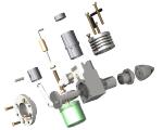

I think I understand 3D CAD now. Here's the next effort using the ML Midge as the subject. Constructing the model was a lot faster than the first effort too, so much so that I'm beginning to think that the effort to results ratio is not vastly disproportionate. The model was rendered by TurboCAD 7.1 in less than a minute. TC 8.2 thrashed my disk for 15 minutes then crashed. That's progress for you!


