| Unless otherwise expressed, all original text, drawings, and photographs on this page created by Gordon Cornell are licensed under a Creative Commons Attribution-Noncommercial-Share Alike 3.0 License. |

|
Model Engine Development
Click on images to view larger picture.
Hover for a description.

Some fifty years ago, my interest in small Internal Combustion engines lead to the production in 1959 of the ED Super Fury. There have been few if any explanitory articles about the design and development of engines in model magazines. This engine would be an ideal subject for model engineers to review and construct.

Over the coming months, new pages will appear that provide complete engineering drawings and constructions steps. It is hoped that this series will lead to a celebration of the engine's introduction and potential use by the Vintage Team Race group and others. In order for this to take place, participants must have sufficient time and resources to construct or restore engines. For those who lack the time or resources, I will also be making a limited batch of replicas to complement this construction series.
Introduction
 On my arrival at Electronic Developments Ltd (ED), development and production was in a poor state. The most recent introduction was the ED Fury, a reed valve induction motor that was not competitive in terms of price and performance. Design and development involves a sequence of procedures where development follows the design stage. Disasters occur when trying to take short cuts. It was apparent that investment had been made in tooling based upon previous experience in making the ED Racer, but despite the numbers made and sold, there were many defects. Problems with pressure die castings for the Racer had not been resolved; there is evidence to support this in the number of variations in crankcase design and material applied. Earlier engine designs had been proven using in-house gravity castings. The fact is that very few engines are original in concept. A review of current and earlier designs only reflects the probable pattern of development and fashion. A failing of this system is that limitations of the original design or concept are rarely made available, or published.
The purpose of the development program is to prove that the proposed engine can be manufactured to the intended standard of performance at an economic price. Production of a single prototype will not be conclusive because the production tooling and process will not have been verified. Manufacture of a batch of components is required to prove design modifications can be repeated. To achieve this, a number of fixtures and tools will be required. These are employed to ensure the components are as near as possible identical. Fixtures are used to secure the item to be machined; gauges are applied to verify dimensions.
My task at ED's was to create a development plan to bring all designs up to a satisfactory production standard to satisfy the bank and directors. Creation of a plan is no simple task. You have to be aware of the current situation before the road to improvement can be established. The plan must be feasible in relation to finance and time scale as there is a significant difference between research and development.
The Development Plan
The basis of any plan must start from verification of the drawings, so as a consequence, all drawings were checked. This was followed by timing all machining operations to establish were improvements could be made. This defined the necessity to specify acceptable limits for manufacture, highlighting deficiencies in methods, machinery and tooling. An overall plan which reflected marketing, manufacture and design arose from this. Action was taken to rectify defective machinery and processes as a consequence of the checking process.All engines had to be tested to determine priority; features which affect all engines can be more important than individual ones. At the time there were no computers to aid design analysis, the method applied was review, modify and test. Originally I used a simple chart to verify my modifications were logical. Today this is supplemented by my computer program, ICE. Where appropriate, this will be used in this series to appraise the design decisions.

The original plan had to encompass all of the ED engine range, but for the purpose of this series, we will confine ourselves to items which led to the introduction of the Super Fury, even though other prototypes did become production items later on. The market was set by the current engines of the period (see chart). There were many more engines on the market—this only reflects 1.5cc compression ignition engines which were considered to be competitive. Designers tended to rely on the reports produced by Ron Warring and Peter Chinn. These reports were the primary source of information for customers at that time. I am unable to confirm if either Ron or Peter ever constructed or developed an engine. Testing engines without an accurate dynamometer can be very misleading. Ron retested many of his early examples following problems with his test rig. He must be credited with his attempts at determining fuel consumption which we will examine in greater detail later in this series. These engine tests ran concurrently with the development of engines for use in team racing leading up to Dick Edmonds win at the first World Championship in 1958.

Readers should appreciate the limitations of these early reports. Ron Warring normally indicated lower peaking speeds than those by Peter Chinn—hence indicated BHP was lower. Ron tested all engines on Mercury No.8 fuel, I found this to be unsatisfactory during the development of the Super Fury. ED also sold bottled fuel which caused rapid build up of carbon deposits, the bottles were a problem hence a change was made to cans. It was important that we supplied the most satisfactory fuel for the engines in current production. As part of the development program Peter Chinn and I developed two new fuels, ED Economic and ED Super Zip. Model Technics D2000 and D3000 fuels have evolved from our co-operation of that period. ED Super Zip gave an increase in excess of 2000 RPM on the Frog 6x4 nylon propeller when compared to Mercury No.8. It was at this point that Isopropyl Nitrate became part of the fuel mixture. What we established was that the fuel did make a difference and that this must be matched to the design and operational speed.


The production engines of that time gave around 0.15 BHP from 1.5cc. My prior developments with the Frog 150R and TR 1.48 both exceeded the 100 BHP/litre mark. The Fury peaking at 14,000 RPM gave only 0.13 BHP (87 BHP/litre). During the development of my TR 1.48, my partner in that project, Peter Frazer, obtained a Super Tigre 1.5cc which featured rotary drum valve induction which gave 0.16 BHP at 16,000 RPM. Information via the model press implied that the new Oliver Tiger Cub Mk 2 was producing 0.17/0.18 BHP at 14,000/16,000 RPM (according to tests by Warring and Chinn—confirmed by published tests in 1961).
Testing
The original prototypes were proven by installation in what are known as team racing models. These are still flown by the BMFA control line section as Vintage models. Vintage Team Race features the best looking model aircraft of the 1950's using motors of the time and their modern reproductions and replicas combined with contemporary racing techniques to deliver some of the most exciting and easily accessible control line racing, at a sensible price. Hence there is an outlet to meet, use and discuss the engines produced. Models of this size fly at 80—100 MPH with engines of this type. International Class models fly at 130 MPH and cost substantial money. The permitted capacity for the engine is 2.5cc hence this is outside the scope and intention of this project. In all cases fuel tank capacity is limited this ensures pit stops take place. The participants rapidly improve there knowledge of fuels and the relationship between BHP and consumption.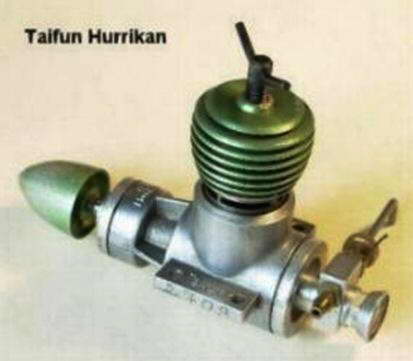 My first team racer had been powered by a Taifun Hurricane which like the ED Fury, had Automatic induction by a reed valve—a fashion of the time. Unfortunately engines with this system can start and run in the reverse direction under light load. Needless to say following a few accidents I decided not to apply this in a racing environment were pit stops are required.

 The second model, named Jumbo Junior, was powered by my TR 1.48, a front rotary vale induction motor. This was competitive with the Oliver Tiger Cub Mk 1. At this time the models were on the small side and very difficult to handle during take off and landing on grass. Propellers made of wood were frequently broken, plastic ones in most cases were not as efficient.
 A larger model named Leveret I was the test bed for the Super Fury. This had a low wing with dihedral and a lifting wing section to aid take off. Leveret II featured a shoulder wing location and proved to be a most satisfactory model. Leveret III—was an update to suit revised rules. The full size drawings were published as a pull-out plan in Model Aircraft for May 1962, together with a the first part of a two-part article on the new class. Scans of all these appear below. The drawings for Leveret II are also still available and for those who do not wish to build Leveret, there is a large range of alternative models on the vintage list. However it is important to have the Center of Gravity (C of G) in the correct position and to ensure that the model design selected is suitable for a rear induction motor
 [Editor's note: Here's the cover from the May 1962 issue of Model Aircraft that Gordon mentions. Click the thumbnail, or follow this link to scans of his two-part series on team racing, complete with plans for the models he mentions. Gordon cautions that the Leveret III may not be suitable for current Vintage 1/2 A Class rules and builders are well advised to check with their associations before cutting wood.]
An alternative to flight testing is to apply RPM checks on a series of commercial propellers. To do this a simple optical tachometer will be required. A Smiths 50000 RPM tachometer was used for the original development. The propeller figures from the original test reports may be impossible to replicate hence a set of figures based upon current commercial items will be established.
| Engine | Capacity | BHP | RPM | Date | Tested by |
|---|---|---|---|---|---|
| AM 15 | 1.5 cc | 0.152 | 14000 | July 1958 | R.Warring |
| AM 15 | 1.5 cc | 0.163 | 15000 | Sept 1958 | P.Chinn |
| ED Fury | 1.49 cc | 0.116 | 12000 | August 1958 | P.Chinn |
| ED Fury | 1.49 cc | 0.13 | 14000 | June 1958 | R.Warring |
| ED Super Fury | 1.49 cc | 0.162 | 14000 | June 1960 | R.Warring |
| ED Super Fury | 1.49 cc | 0.172 | 14500 | Aug 1960 | P.Chinn |
| ED Super Fury | 1.49 cc | 0.232 | 17500 | June 1962 | P.Chinn |
| ED Super Fury Mk 2 | 1.49 cc | 0.21 | 17500 | May 1970 | P.Chinn |
| Elfin BB Reed Valve | 1.49 cc | 0.158 | 13600 | Jan 1955 | R.Warring |
| Frog 150R | 1.48 cc | 0.152 | 14500 | July 1958 | P.Chinn |
| Frog Viper Drum Valve | 1.48 cc | 0.161 | 14800 | April 1961 | R.Warring |
| Oliver Tiger Cub Mk 2 | 1.46 cc | 0.186 | 16000 | April 1961 | P.Chinn |
| Oliver Tiger Cub Mk 2 | 1.46 cc | 0.17 | 14000 | Aug 1961 | R.Warring |
| PAW | 1.49 cc | 0.17 | 16000 | Sept 1959 | P.Chinn |
| PAW | 1.49 cc | 0.176 | 17000 | March 1960 | R.Warring |
| Super Tigre G31 | 1.47 cc | 0.16 | 16000 | Nov 1957 | P.Chinn |
| Taifun Hurrikan | 1.48 cc | 0.153 | 14500 | Jan 1957 | R.Warring |
Table 1: Published Engine Reviews.
Constructing a Replica Super Fury
, Disc Valve (right)") For those that wish to make a start immediately, a complete sets of drawings are available in digital image (pdf) and portable CAD (dxf) formats. From these, you can construct replicas and variants produced during the original process and subsequently. Drawings will be included as components are evaluated in terms of their effect on performance. It will be possible for constructors to experience the process of development and determine if the decisions made at the time were correct. In addition there appears to be no logical reason why constructors should not incorporate there own ideas and modifications. However if the engine produced is to be used in Vintage team racing acceptability of the intended modifications should be verified. The current rule book can be downloaded from the BMFA web site.
For those that wish to make a start immediately, a complete sets of drawings are available in digital image (pdf) and portable CAD (dxf) formats. From these, you can construct replicas and variants produced during the original process and subsequently. Drawings will be included as components are evaluated in terms of their effect on performance. It will be possible for constructors to experience the process of development and determine if the decisions made at the time were correct. In addition there appears to be no logical reason why constructors should not incorporate there own ideas and modifications. However if the engine produced is to be used in Vintage team racing acceptability of the intended modifications should be verified. The current rule book can be downloaded from the BMFA web site.
It has been established that a quantity of spares from ED's 1970 production are available. Unfortunately there are no crankcases and some of the components have been made to suit the Super Fury Mk 2—this was not made by the original company hence the quality may not be to the same standards (materials and heat treatment are different). These parts could be used to restore original such engines as still exist, or they might be used by constructors who are unable to manufacture components to a satisfactory standard.
 Crankcase
Drum Valve
Disc Valve
Cylinder
Crankshaft
Carburettion
Automatic Induction
Performance Evaluation
Crankcase
Drum Valve
Disc Valve
Cylinder
Crankshaft
Carburettion
Automatic Induction
Performance Evaluation
Support Services
For BMFA membership contact:
BMFA
Chacksfield House
31 St Andrews Road
Leicester LE2  8RE
Telephone 0116 2440028
Vintage Team Race:
ED Spares:
Drawings


This page designed to look best when using anything but IE!
Please submit all questions and comments to
enquiries@modelenginenews.org