Development of AHC Diesel Prototype
Created: May 2001
Last Update: July 2007
Click on images for larger picture
In this section, you will see and read about the very simple tooling and fixtures developed to make building a small production run of AHC Diesels a practical proposition. As I've said elsewhere, I have no formal training in machining, or manufacturing—I'm a software development engineer! The material presented here is intended for your amusement, not your education.
 Photo 1 |
 Photo 2 |
 Photo 3 |
 Photo 4 |
 Photo 5 |
 Photo 6 |
 Photo 7 |
 Photo 8 |
 Photo 9 |
 Photo 10 |
 Photo 11 |
 Photo 12 |
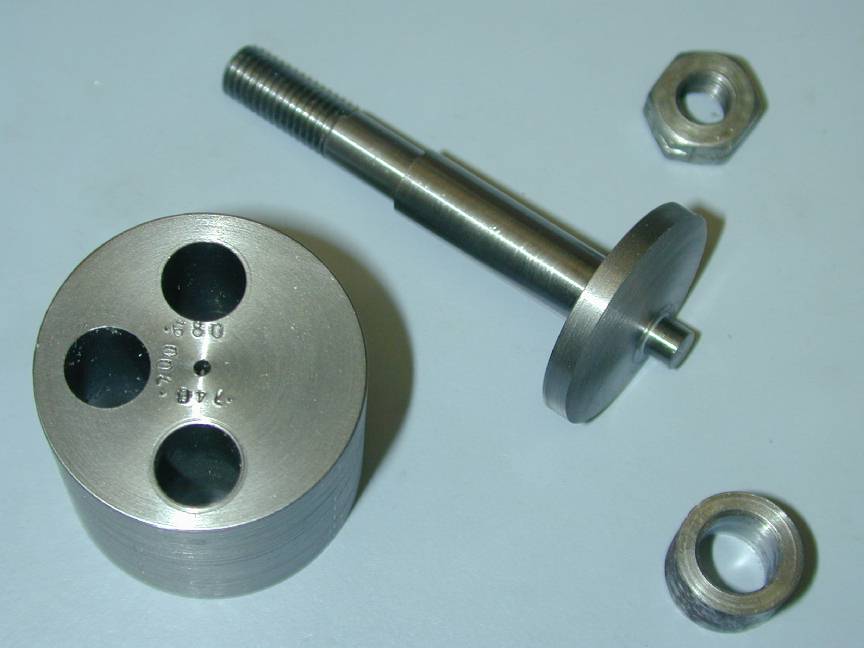 Photo 13 |
 Photo 14 |
 Photo 15 |
 Photo 16 |
 Photo 17 |
 Photo 18 |
 Photo 19 |
 Photo 20 |
 Photo 21 |
1. Bert's Crankcase Fixture
The most important thing to get right when machining crankcases is to get the cylinder and shaft bores at precisely 90 degrees to each other--any misalignment will send friction through the roof. We can achieve this on the AHC case by using the back face as a reference. Here's a simple jig made by Bert Striegler to bore the case for the shaft bearing. The case is secured by four 4-40 screws and the jig mounted in the 4JSC chuck.
back...
2. Ron's Crankcase Fixture
Here's my variation on Bert's design. Basically, it's the same but as I intend making a lot more engines than Bert, I did not want to have to remove the fixture from the chuck to change the case, hence, my fixture secures the case using clamps over the backplate lugs. The central spigot ensures the bore will be concentric with the case cavity and a single pin engages in one lug hole to ensure repeatability and take the driving forces (I drilled for four pins, but decided one was quite enough). Testing a few cases in this fixture suggests that the cases were popped from the die too hot and have suffered distortion resulting in the end of the journal not being concentric with the internal case cavity. The worst I've measured so far is 0.1" (over 3/32", or 2.3mm) out of true!
back...
3. Case in Shaft Boring Fixture
Here's a reject case being used to test the fixture. The kindest term for the "metal" used in the casting is "pot metal", so called because it could have come from melted down pots and pans. It's sorta grey and comes off in grains rather than curls. Still, with a really sharp tool and lots of suds, it can be machined ok. Normal procedure is to drill and ream a case. Unfortunately, a lot of the cases have been drilled by a previous project custodian, centered in the end of the protrusion which means the bore is NOT concentric with the case cavity due to the distortion mentioned above. These can be fixed by boring oversize until the eccentricity disappears. The down side is they require a non-standard bushing be custom fitted. I'm certainly not going to get rich on this job.
back...
4. Inlet Machining Fixture
The inlet for the AHC is cast into the case as a long, spindly, delicate protuberance. I suspect AHC would have done brisk business in replacement cases if this thing had reached the market and been flown in any numbers. This too, has suffered the droopies in random directions so the only way to hold for machining is to align the stem vertically and let the case position where it will. The fixture shown is slot drilled to be a snug fit around the inlet end and the spray bar boss. A 4-40 screw bears against an ejector pin mark to secure the case during the job. A captive copper pad prevents the case being marked by the screw. This trick came from George Thomas writing in Model Engineer. Just make a thin copper plug that drops into the threaded hole. Tighten up the screw and the plug gets squished into the thread, expanding enough so if won't drop out, but able to move enough to act as a protecting pad. Neat.
back...
5. Inlet Drilling
The jig acts as a drilling guide and ensures the drill enters axially, concentrically and does not wander. If I was going to machine a lot of cases, this jig would sport a hardened guide button, but for the number I'm planning on completing, soft should be fine. Drilling is taken slowly, with lots of suds and frequent withdrawal to clear away the chips.
back...
6. Drilled Case
The inlet drilling jig, rotated 90 degrees is also used to face, drill and tap the spray bar boss (operation not shown here). First, the drill guide hole is used to position the milling vice. This assures the spray bar will be accurately centered and at right angles to the venturi bore. Facing at the same setting provides good seats to the two piece needle support insert and fuel jet.
back...
7. Cylinder Boring Fixture
This fixture again uses the rear face of the case as the datum to bore the cylinder passage, set the "deck" height and cut the thread for the cylinder head. Note the two pins. These engage in the top two backplate lugs and also bear against the angle plate to align the jig. A 1/4-20 cap head screw pushed the case firmly against the jig. Note how the spigot has been milled flat (in the plane of the pins) to allow the deck height to be easily measured using the depthing capability of a Vernier calliper. This face has also been center drilled after the jig was aligned so it can be re-aligned with a wobbler and DTI.
back...
8. Case in Cylinder Fixture
Here's a case being finished. First, a 3/4" end mill is used to open out for the head thread and to set the deck height. This also trues up the top opening. The thread can then be cut, checking it against a "master" thread gauge. Next the case is opened out to 9/16" diameter for the cylinder. My tests have done this by boring, but in "production", I plan on using a reamer. As the bypass is cast into the case, a spiral flute reamer will be needed as the transfer cavity would cause a straight flute reamer to wander.
back...
9. The AHC Fixture Collection
Some of the fixtures are shown here. The long bar on the left is used to bend the compression screw end. It has a radiused opening. The anular thing is a pot-chuck used to hold the knurled prop driver for finishing the back face and tapering for the split drive collet. The smaller of the two buttons is threaded 10-32 to hold the screwed portion of the compression screw while the operator end is taper turned and to protect the thread while the operator portion is bent over. It is split so that tightening the 3JSC chuck will grip the thread tightly. The other button is threaded 8-32 hold the spray bar components for drilling and "external" machining. The last button on the right is a retread from the Vivel project. It has a 1/4-28 stud and holds spinner nuts for final shaping. The round gadget in the middle of the back row holds the cylinder head blanks for fin cutting. The concentric plug screws up and down on a 1/4-20 cap head bolt. It acts as a go/no-go gauge when opening out the head cavity and also as a stop to prevent the head tightening itself up too tight under fin cutting forces. The internally threaded part of this fixture also acts as a thread gauge for the heads. How's that for multi-tasking? Virtually all these fixtures were made from the scrap box.
back...
10. Cylinder Lap and Holding Fixture
The cylinder lap is my standard aluminium, spilt lap, expanded by a screw in a hole threaded with a #1 (taper) tap. Crude, but works very well giving surprisingly fine, incremental adjustment. The expertly made and lovingly finished (??!) cylinder holder is a drilled and split block that slips over the bare cylinder. The operator provides the clamping pressure by gentle squeezing. This lap got quite chewed up on burrs left inside the bore following port cutting. The bore is nominally 31/32", not a size reamer I have, but I may "invest" so I can size them (by floating in the reamer) and also use it to clear any burrs before lapping (for detailed words on lapping and lap charging, see the Weaver Construction Log).
back...
11. Piston Fixtures
The T shaped thinggy is used to hold pistons for final turning and honing. The cross-drilled shaft telescopes inside the stepped outer body. When making pistons, the interior of a cast iron blank is finish machined, then drilled and reamed for the wrist pin (or "gudgeon" pin if you are of the British persuasion). The brass pin engages in the wrist pin holes and is pulled back by the socket head screw, pulling the piston interior step onto the top of the jig. Obviously the fixture needs to be removed from the chuck to change the piston, but as final turning is done using this jig, this presents no great problem. The small aluminium mandrel in this photo is machined with a 1 degree taper for a press fit in the interior of the contra pistons. This holds them for OD turning and finishing per the "David Owen, Sure-Fire Contra-Piston Fit" method described in the Taplin Twin Construction feature. The fixture is drilled and threaded so a screw can be inserted to pop the C-P off the mandrel when fitting is complete. The curved plate is a form tool used to finish the spinner nuts.
back...
12. Taper Mandrel for Main Bearing
For a long time, I thought tapered mandrels had to taper over their entire length (stop laughing!)—finally I found out better from a throw-away line in an SIC article. Now it makes sense. Taper mandrels are used to hold work that is finished internally and needs the outside turned with a high degree of concentricity. The production AHC's will use re-worked cast iron valve guides as main bearings. This relieves me of the effort required to ream the bush. That's one in this photo. Each guide will produce two bushes. The mandrel is a close sliding fit in the bush at the front, produced by turning between centers. The undercut leads into the actual tapered part of the mandrel which tapers at about 1.5 degrees included, going from under the bush ID (5/16"), to just over the ID, so that the bush jams tight about half way along the tapered section. The OD can then be turned (between centers) to give a high degree of concentricity. Note that all cutting forces tend to push the work further onto the mandrel. As we are working between centers, the work and mandrel can easily be removed from the lathe for testing in the case hole and replaced for further machining with no loss of precision. A sleeve is finally used to tap the finished bush from the taper.
back...
13. Crankpin Fixture
No, not the chamber for a home made four-shooter, this is a simple fixture for turning crankpins with minor variations in throw. The original plans called for a 0.700" throw. Somehow, I goofed (again) and ended up with a fixture that produced .740" of throw. This required thinning the rod and finally, grinding away the case for additional rod clearance. For the "production run" I did not want to have to do this, so the fixture got additional holes made to put the throw in the right place and while I was at it, to give a little less throw (0.680"). Obviously, the fixture (steel in this case) is drilled and reamed off center by one half the total throw required. Common practice is to either slit the fixture so the chuck supplies clamping force, or to put set screws with soft shaft protecting pads under them to prevent the rod turning in the fixture. A much simpler and more secure solution is to use a nut (1/4-28 in this case) to make the crank hold itself in the jig. The spacer is needed because the scrap I used was too short overall.
back...
14. Turning the pin.
In use, the fixture simply goes into the 3JSC chuck and away we go. I've tried turning pins by both successive longitudinal and lateral cuts. I favour the latter as shown under way here because there's no "critical point" at which the self-act must be disengaged and a long, interrupted cut is avoided. The pin is turned oversize by progressive 0.025" shavings, starting at the pin and cutting towards the operator. When the full length of the pin, less 10 thou is achieved, cutting is changed to longitudinal for finishing to size. A final pass over the web is then made to clean up face. Con rod big ends need lubrication and for this you need some clearance in the hole. Racing engines use up to 0.003". I use about 1 to 2 thousandths of an inch. This also assists in assembly as the rod with piston attached is jiggled onto the crank pin.
back...
15. Crank in Jig
The same jig is used to hold the shaft vertically under the mill to machine out the web counterbalance. Here we see it just before this step. The spacer under the web provides tool clearance for the 3/4" end mill that will cut the crescents out.
back...
16. Profiling the Rod Ends
Some more very simple tooling comprising a pair of buttons corresponding to the diameter of the rod ends with stems matching the inside diameter are used to hold the rods against a 1/8" end mill to profile the ends. The rod is swung by hand so that all cuts are "climbing cuts" (ie, the work moves against the direction of cutter rotation). Cutting in the opposite direction has a tendency to snatch the work and mill away the rod shank, requiring the use of strong language. After milling, the OD is buffed on a Scotch-Brite &mark; belt producing a very smooth finish and "breaking" the sharp edges left by the milling. I'm often amazed at how close photographs make parts appear much rougher that they seem to the naked eye.
back...
17. Exploded Parts View
Here's an AHC laid out for final assembly. The shallow, stamped backplate is clearly visible together with its thick gasket that will seal it against the un-machined case opening. At this point, the shaft counter balance cut-outs have not yet been milled (I forgot!) Sharp-eyed readers will notice this is the "01" engine, not the "00" prototype.
back...
18. Second Prototype
Putting the cart before the horse, this is the 01 engine. Main differences are the reduced capacity resulting from smaller throw, and the reduced base diameter of the spinner to produce a more needle nosed, "deadly" look approximating that of the original engine photograph at the head of this page.
back...
19. Prototype "Sixty-One Zero-Zero"
This AHC was built as the jigs and fixtures were being made. It uses a reject case (notice the ding in the front of the right hand mounting lug). I call it the 61-00 engine. "00" because it's the prototype and I can't make more than about 90 engines (limited by case availability); "61" because that's the ISD code for Australia where this AHC was made. When this shot was taken, 61-00 lacked pistons and rod. If you look closely, you can just see the "00" in the ejector pin mark on the needle boss.
back...
20. First Test Run of 61-00
The prototype ran for the first time on Anzac Day, April 25, 2001. It started easily and handles well. Initial start used a 12" diameter, 7-1/2" pitch "Deci Ban" wood prop because I'd made the "pinch" in the piston/cylinder fit quite tight, so I wanted a lot of flywheel for first start. In normal use, this is far too much prop for an engine of just under 2cc capacity. However, on this prop, at its first start, it ran a full 10cc tank dry in about 4:30 minutes—very, very economical. Best RPM on this prop was 3500. Next it spun a 9-6 wood at 5500 RPM and an 8-4 plastic at 6500. As an experiment, I did not machine out the crankshaft counter balances in the web for the first tests (ok, I admit it, I forgot). During this test session, the engine was given about 30 minutes of running. At the end, a 9-6 APC prop was giving a consistent 6000 RPM.
back...
21. 61-00 Second Test Run Session
The engine was then pulled down for inspection and crank web machining. It had run cleanly (meaning the bores were well aligned and no metal was being worried away). Inspection showed things were bedding in nicely, although there was a slight sideways bend in the bottom of the 1/8" 2024 T3 aluminium rod. I'd had to machine this narrower than I wanted to get interior case clearance. The 01 engine will reduce the throw slightly so the rod width/strength can be improved. After machining the crank "balance" weight and reassembling, the AHC restarted on the first flick! It now turned the APC at 6500 RPM—a significant improvement and justification of this practice. I'm not totally happy with the performance and I suspect, based on the sound alone, that it is four cycling (ie, firing on alternate strokes), though I could be wrong. This could be due to the very narrow inlet diameter (0.125"). It can be increased somewhat, but not a lot. Next trial will investigate the effect of opening it to 0.140"—the tapping size for 8-32 which is the thread of the needle valve inserts.
back...
![]()

Please submit all questions and comments to enquiries@modelenginenews.org